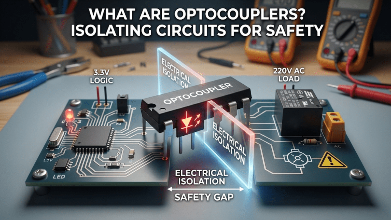
An optocoupler (also called optoisolator or opto-isolator) is a component that transfers electrical signals between two isolated circuits using light, with no electrical connection between them. It consists of an LED on the input side and a photodetector (usually a phototransistor) on the output side, both sealed in an opaque package. When current flows through the LED, it emits light; the photodetector receives this light and conducts current proportionally. This light-based coupling provides electrical isolation of thousands of volts between input and output—protecting sensitive low-voltage electronics from high-voltage transients, preventing ground loops in audio systems, and meeting safety requirements for medical equipment and industrial control systems.
Introduction: Isolation Through Light
Every practical electronic system eventually faces the challenge of interfacing circuits that must communicate but should never share an electrical connection. A microcontroller needs to monitor the status of a mains-powered motor without exposing its delicate 3.3V logic to 240V spikes. An audio mixer must connect multiple pieces of equipment without creating ground loops that cause hum. Medical equipment must measure patient signals while guaranteeing that no dangerous current can flow from the mains-powered equipment to the patient.
These challenges all require galvanic isolation—a complete electrical separation between two circuits such that no current path exists between them, yet signals can still transfer across the barrier. Transformers provide this for AC signals through magnetic coupling. Relays provide it for power switching through mechanical actuation. And optocouplers provide it for signals—including DC, logic levels, and analog voltages—through optical coupling.
The fundamental elegance of an optocoupler is its operating principle: light carries the signal. The input side converts an electrical signal into light using an LED. The output side converts that light back into an electrical signal using a photodetector. Light travels across a transparent insulating barrier (typically 1–2mm of clear plastic or silicone), completing the signal transfer. But light doesn’t conduct electricity—there is absolutely no electrical path, no shared ground, no way for high voltages or transient spikes on one side to reach the other except through electromagnetic radiation (light), which is harmless.
This physical separation matters profoundly in applications where isolation is not a design nicety but a safety requirement. When isolation is specified in the kilovolt range, it means that voltages of thousands of volts applied across the barrier will not break down the insulation and create a conduction path. This is what allows optocouplers to protect human life in medical equipment, protect expensive equipment from ground faults, and meet regulatory requirements for mains-connected consumer electronics.
This comprehensive guide explores optocouplers from physics through practical application: the LED-photodetector mechanism, the specifications that define performance, the various types for different applications, design calculations for proper operation, common circuits using optocouplers, and when optocoupler isolation is the right choice versus alternatives.
Part 1: How Optocouplers Work — Light as the Medium
The Basic Structure
Every optocoupler contains four fundamental elements:
1. Input LED: An infrared LED (typically 940nm wavelength) on the input side. When forward current flows through this LED (I_F, typically 5–20mA), it emits light proportional to the current.
2. Photodetector: A light-sensitive semiconductor on the output side. Common types:
- Phototransistor: Most common; acts as a transistor with base current determined by incident light
- Photodiode: Faster response but lower gain
- Photo-Darlington: Higher gain but slower than phototransistor
- Photo-triac: For AC switching applications
3. Transparent insulator: Clear plastic or silicone that allows light to pass while providing electrical insulation rated for kilovolt isolation.
4. Opaque package: Blocks external light from reaching the photodetector, ensuring only the internal LED light controls the output.
The Transfer Mechanism
Input to light: The input circuit drives current through the LED. LED brightness is proportional to forward current I_F (within operating range). More current = more light emitted.
Light to output: Light from the LED strikes the photodetector. In a phototransistor optocoupler, the light generates electron-hole pairs in the base region, creating base current. This base current is amplified by the transistor’s current gain (β), producing collector current I_C.
The coupling: Output current is proportional to input current, with the proportionality constant called the Current Transfer Ratio (CTR):
CTR = (I_C / I_F) × 100%
Typical CTR values: 20% to 200% depending on optocoupler type.
A CTR of 50% means: if I_F = 10mA, then I_C = 5mA (when the output transistor is operating in the active region, not saturated).
Why there’s no electrical connection: The LED and photodetector share no wires, no conductors, no common ground. They are physically separate semiconductor dice mounted on opposite sides of the insulating barrier. The only medium of communication is photons—light particles that travel across the gap but carry no electric charge and cannot conduct electricity.
The Isolation Barrier
The distance between the LED die and photodetector die, plus the high-dielectric-strength plastic or silicone between them, determines the isolation voltage rating.
Isolation voltage: The maximum voltage that can be applied across the barrier (between input ground and output ground) without breakdown.
Common ratings:
- Standard: 2.5kV–3.75kV (for general industrial use)
- Reinforced: 5kV–10kV (for medical and high-reliability applications)
- Ultra-high: >10kV (special applications)
What isolation voltage protects against:
- High-voltage transients on one side (lightning, inductive spikes, mains faults)
- Ground potential differences (ground loops eliminated by no shared ground)
- Accidental connection of high voltage to low-voltage circuit (human error protection)
Part 2: Key Specifications and Characteristics
Current Transfer Ratio (CTR)
CTR defines how efficiently the optocoupler transfers current from input to output.
CTR = (I_C / I_F) × 100%
Where:
- I_F = LED forward current (input)
- I_C = Collector current (output, measured with fixed V_CE)
CTR variation: CTR is not constant:
- Varies with LED current (increases then saturates)
- Decreases over device lifetime (LED aging)
- Varies between devices even from the same batch (wide manufacturing spread)
- Temperature-dependent (typically decreases at high temperature)
Design implication: Never design circuits that rely on precise CTR values. Use the minimum CTR from the datasheet for worst-case design, then overdrive the LED to ensure adequate output even with lowest CTR.
Forward Voltage (V_F) and LED Current
The input LED has a forward voltage drop like any LED: V_F ≈ 1.1–1.5V (typical for infrared LED)
Input current is set by the driving circuit: I_F = (V_source – V_F) / R_series
Typical operating range: 5–20mA Absolute maximum: Often 50–60mA (check datasheet)
Higher I_F:
- Produces more light → higher output current
- Increases power dissipation in LED
- Accelerates LED aging (shortens device lifetime)
Design for I_F in the 10–20mA range for good performance without excessive aging.
Switching Speed
Optocouplers are slower than direct electrical connections:
Turn-on time (t_on): Time for output to respond after input is applied. Typically 1–10μs.
Turn-off time (t_off): Time for output to turn off after input is removed. Typically 3–100μs (often slower than turn-on because of stored charge in photodetector).
Rise time / fall time: Time for output to transition between 10% and 90% of final value.
Bandwidth / propagation delay: For high-speed digital optocouplers, specified in Mbps or propagation delay in nanoseconds.
Limitation: Standard phototransistor optocouplers are too slow for high-speed data (>100kbps). For fast digital signals, use:
- High-speed optocouplers (with integrated logic)
- Capacitively-coupled digital isolators (not light-based, but serve similar role)
Isolation Voltage and Creepage/Clearance
Isolation voltage (V_iso): Rated voltage that can be applied continuously across the barrier. Test voltage is typically 2× the rated working voltage.
Creepage distance: The shortest path along the surface of the insulating material between input and output pins.
Clearance distance: The shortest distance through air between input and output pins.
Safety standards (UL, VDE, IEC 60747-5) specify minimum creepage and clearance for given isolation voltage ratings.
For reinforced insulation (medical, industrial safety), both distances typically ≥8mm for 5kV isolation.
Part 3: Types of Optocouplers
Phototransistor Output (Most Common)
The standard optocoupler uses an NPN phototransistor as the photodetector.
Configuration: LED input → Phototransistor collector and emitter accessible as output
Characteristics:
- CTR: 20%–200% typical
- Speed: Moderate (t_on ~10μs, t_off ~50μs)
- Output: Acts like NPN transistor switch
- Applications: General digital isolation, relay driving, logic level translation
Popular devices:
- 4N25, 4N35, 4N28: Classic general-purpose
- PC817: Very common in industrial applications
- 6N137: High-speed with internal logic output
Photo-Darlington Output
A Darlington pair (two transistors in cascade) provides higher current gain than a single phototransistor.
Characteristics:
- CTR: 100%–600% (much higher than standard)
- Speed: Slower (t_off can be >100μs due to two-transistor storage time)
- Lower LED current needed for same output current
- Applications: Where high gain needed; low-speed relay driving
Trade-off: Higher gain but slower switching makes photo-Darlington suitable only for low-frequency applications (Hz to low kHz range).
Photodiode Output
Uses a photodiode instead of phototransistor. The photodiode generates current proportional to light, which can be amplified externally.
Characteristics:
- Very fast (nanosecond response)
- Low gain (requires external amplifier)
- Linear response over wide range
- Applications: High-speed data transmission, linear analog isolation
Logic Output (High-Speed Digital)
Integrated circuit on the output side provides logic-level output compatible with TTL or CMOS.
Example: 6N137
- Built-in output buffer provides logic HIGH/LOW directly
- Speed: 1Mbps+ data rates possible
- Propagation delay: 50–100ns
- Applications: Isolated UART, SPI, I²C, RS-485 isolation
Photo-Triac and Photo-SCR
Output is a light-triggered triac or SCR for AC switching applications.
Characteristics:
- Directly drives triac or SSR for AC load control
- Zero-voltage crossing options available (switch only when AC voltage crosses zero, reducing EMI)
- Applications: Isolated AC switching, motor control, lighting control
Typical device: MOC3021, MOC3041 (with zero-crossing detector)
Linear (Analog) Optocouplers
Specialized optocouplers designed to transfer analog signals with high linearity.
Method: Two matched LEDs or feedback loop maintains linear transfer.
Applications:
- Isolated sensor amplifiers
- Isolated analog voltage/current measurement
- Audio isolation (though transformers often preferred)
Challenge: LED aging causes drift; feedback compensation circuits required for long-term stability.
Part 4: Practical Optocoupler Circuits
Digital Signal Isolation (MCU to MCU)
Isolating a digital signal between two microcontrollers with separate ground systems:
MCU1 Side (Input):                 MCU2 Side (Output):

MCU1 GPIO ──[330Ω]──┬─ LED Anode     Collector ─┬── MCU2 GPIO
                    │                           │
                   [4N25 Optocoupler]      [10kΩ Pull-up to VCC2]
                    │                           │
        GND1 ──────┴─ LED Cathode    Emitter ──┴── GND2

No connection between GND1 and GND2!Design calculation: Assume MCU1 GPIO = 3.3V, V_F = 1.2V, target I_F = 10mA R_series = (3.3V – 1.2V) / 10mA = 210Ω → Use 220Ω or 330Ω
CTR_min = 50% (from datasheet) I_C = CTR × I_F = 0.5 × 10mA = 5mA (minimum)
Pull-up resistor on output: R_pullup = VCC2 / I_C_desired For VCC2 = 5V, want I_C = 5mA when saturated: R_pullup = 5V / 5mA = 1kΩ → Use 1kΩ or higher (10kΩ is common, reduces current)
Operation:
- MCU1 HIGH → LED on → Phototransistor conducts → Pulls MCU2 input LOW
- MCU1 LOW → LED off → Phototransistor off → Pull-up brings MCU2 input HIGH
Note the inversion: input HIGH → output LOW. This is typical for phototransistor optocouplers.
Mains Zero-Crossing Detector
Detecting when AC mains voltage crosses zero (for phase control, synchronized switching):
Mains AC ──[1MΩ, 2W]──[Bridge Rectifier] ──┬─ LED Anode
                                           │
                                       [Optocoupler 4N25]
                                           │
                GND_isolated  ─────────────┴─ LED Cathode

                                      Collector ─┬── MCU GPIO
                                                 │
                                            [10kΩ to VCC]
                                                 │
Emitter ──┴── MCU GNDOperation: When mains voltage is away from zero, sufficient voltage rectified to drive LED → output LOW When mains voltage near zero, insufficient voltage → LED off → output HIGH (pulled up)
MCU detects rising edge on GPIO → mains zero crossing detected → triggers phase-angle control
Safety: 1MΩ current-limiting resistor rated for at least 2W dissipation, and bridge rectifier rated for mains voltage.
Isolated Relay Driver
Using optocoupler to drive a relay from a microcontroller while completely isolating the relay’s power supply and load:
MCU Side:                          Relay Side:

MCU GPIO ──[330Ω]─┬─ LED          Collector ──[Relay Coil]── VCC_relay
                  │                        │
              [4N25]                  [Flyback diode]
                  │                        │
     MCU GND ─────┴─ LED          Emitter ────── GND_relay

VCC_relay can be 12V, 24V, or even 240V (through appropriate high-voltage driver)
This circuit provides complete isolation—the relay and its load can operate at any voltage independent of the MCU supply.
Ground Loop Elimination in Audio
Professional audio systems use optocouplers (or transformers) to break ground loops that cause 60Hz hum:
Equipment 1 GND                    Equipment 2 GND
      │                                  │
   Audio Out ─────[Digital Audio]────── Audio In

                  [via Optocoupler]
      │                                  │
Earth 1 ───── No connection ────── Earth 2Even though Equipment 1 and Equipment 2 are both grounded to earth (which may be at different potentials, creating ground loops), the audio signal passes through an optocoupler with no electrical connection—eliminating hum.
Motor Controller Isolation
High-power motor drivers often use optocoupler isolation between low-voltage control logic and high-voltage/high-current switching:
MCU → Optocoupler → Gate Driver → IGBT/MOSFET → Motor

The optocoupler isolates the delicate MCU from:
- High-voltage supply (hundreds of volts)
- Current spikes and EMI from motor switching
- Ground bounce from high di/dt switchingPart 5: Design Considerations and Best Practices
Designing for Minimum CTR
CTR varies widely:
- Between devices (manufacturing tolerance)
- Over temperature (decreases at high temp)
- Over lifetime (LED degrades, CTR drops)
Rule: Always design using the minimum CTR specified in the datasheet, then verify the circuit works over the full CTR range.
Example: Datasheet specifies CTR = 50%–200% at I_F = 10mA Design for CTR_min = 50%
If you need I_C = 5mA minimum: Required I_F = I_C / CTR_min = 5mA / 0.5 = 10mA
Even if a particular device has CTR = 200%, the circuit must work correctly—check that higher CTR doesn’t cause problems (saturation issues, unexpected behavior).
LED Resistor Calculation
Standard formula: R_LED = (V_drive – V_F) / I_F
Account for voltage variation: If V_drive can vary (e.g., 3.3V ±10%), calculate for worst case: R_LED = (V_drive_min – V_F_max) / I_F_target
Example: V_drive = 3.3V ±10% → minimum 2.97V V_F_max = 1.4V (from datasheet) I_F_target = 10mA R_LED = (2.97V – 1.4V) / 10mA = 157Ω → Use 150Ω (closest standard, slightly higher current acceptable)
Pull-Up/Pull-Down Resistor Selection
The phototransistor output is open-collector/open-emitter—requires external pull-up or pull-down.
Pull-up resistor (most common): When phototransistor is off, pull-up brings output HIGH When phototransistor conducts, it pulls output LOW
R_pullup selection trade-off:
- Too low: High current when transistor conducts (wastes power, heats transistor)
- Too high: Slow rise time when transistor turns off (R × C_load time constant)
Typical values: 1kΩ–10kΩ for digital logic For faster switching: Use lower values (470Ω–1kΩ)
Ensuring Isolation Integrity
The optocoupler provides isolation only if the PCB layout respects the isolation barrier:
PCB design rules:
- Maintain creepage/clearance distances between input-side and output-side traces (minimum 8mm for reinforced insulation)
- No ground plane bridge across the isolation barrier
- Route input signals on one area of board, output signals on another, with physical separation
- For multi-layer boards, ensure inner layers also respect the barrier (no copper bridge)
Violating isolation through PCB layout defeats the entire purpose of the optocoupler.
Preventing Latch-Up in CMOS Outputs
High-speed optocouplers driving CMOS logic can cause latch-up if the optocoupler’s output edges are too fast or if the CMOS input sees voltages outside its supply rails during power-up.
Prevention:
- Add a small series resistor (22–100Ω) between optocoupler output and CMOS input
- Ensure output-side VCC powers up before or simultaneously with the optocoupler receiving signals
Part 6: Optocoupler vs. Other Isolation Methods
Understanding when to use an optocoupler versus alternatives:
Optocoupler vs. Relay
| Aspect | Optocoupler | Relay |
|---|---|---|
| Isolation mechanism | Light (photons) | Magnetic + mechanical |
| Speed | μs to ns (depending on type) | ms (mechanical inertia) |
| Lifespan | Essentially unlimited switching | Limited by contact wear |
| Power handling | Low (mA to ~100mA for photo-output) | High (A to 100A+ for contactors) |
| Isolation voltage | 2.5kV–10kV+ | Complete (no voltage limit from mechanism) |
| Signal type | DC, logic, analog, low-frequency AC | AC or DC power, any voltage |
| Size | DIP-4, DIP-6, SMD packages (small) | Larger (relay size) |
| Cost | Low ($0.10–$2) | Low to moderate ($0.50–$5) |
| Audible noise | Silent | Clicking |
| Best for | Signal isolation, logic, data | Power switching, high current |
Optocoupler vs. Transformer
| Aspect | Optocoupler | Transformer |
|---|---|---|
| Isolation mechanism | Light | Magnetic field |
| Signal type | DC, logic, AC | AC only (can’t pass DC) |
| Frequency range | DC to MHz (digital types) | Audio to RF (depends on design) |
| Size | Small (IC package) | Larger (wire wound) |
| Bandwidth | Limited by switching speed | Can be very wide (RF transformers) |
| Best for | DC and logic isolation | AC signal isolation, impedance matching |
Optocoupler vs. Digital Isolator
Modern capacitive/magnetic digital isolators (e.g., TI ISO7xxx, Analog Devices ADuM) compete with optocouplers:
| Aspect | Optocoupler | Capacitive/Magnetic Isolator |
|---|---|---|
| Technology | LED + photodetector | Capacitive or transformer coupling |
| Speed | 1Mbps (standard) to 50Mbps (fast) | 150Mbps to 600Mbps |
| Power consumption | Higher (LED always on) | Lower (only during transitions) |
| Temperature stability | CTR varies with temp | Better stability |
| Aging | LED degrades over time | Minimal aging |
| Cost | Lower | Higher |
| Isolation voltage | 2.5kV–10kV | 2.5kV–5kV typical |
| Best for | Cost-sensitive, proven designs | High-speed data, precision |
Comparison Table: Optocoupler Types
| Type | Speed | CTR | Output Type | Best Application |
|---|---|---|---|---|
| Phototransistor | Slow–Medium (10μs) | 20%–200% | Open-collector NPN | General digital isolation, relay drive |
| Photo-Darlington | Slow (>50μs) | 100%–600% | Open-collector | High gain, low-speed relay drive |
| Photodiode | Fast (ns) | Low (<10%) | Current source (needs external amp) | High-speed analog, precision |
| Logic output | Fast (50ns–1μs) | N/A | TTL/CMOS compatible | High-speed digital, isolated UART/SPI |
| Photo-triac | Medium (AC) | N/A | Triac gate drive | AC switching, motor control |
| Linear | Medium | Controlled feedback | Proportional voltage/current | Isolated sensors, analog signals |
Conclusion: Invisible Light, Visible Safety
The optocoupler achieves something remarkable: it allows signals to cross an isolation barrier of thousands of volts while being physically smaller than a dime and costing less than a dollar. The mechanism—converting electricity to light and back again across a millimeter of plastic—is conceptually simple, yet the safety implications are profound.
Core Principles Reviewed
Light provides perfect electrical isolation. Photons carry no charge. The LED and photodetector share no electrical connection—only photons cross the barrier. This makes isolation failures nearly impossible short of physical package destruction.
CTR varies widely; design for minimum. Current transfer ratio is not a precise specification. Design conservatively using datasheet minimum CTR, then verify behavior across the full range.
Isolation is only as good as the PCB layout. An optocoupler rated for 5kV isolation provides zero protection if PCB traces on input and output sides are spaced 1mm apart. Creepage and clearance distances must be respected in layout.
Speed limitations matter for high-frequency signals. Standard phototransistor optocouplers are too slow for high-speed data. For >100kbps, use high-speed optocouplers or modern digital isolators.
Optocouplers bridge worlds. They enable microcontrollers to safely monitor mains-powered equipment, industrial sensors to communicate with control systems, and medical devices to measure patient signals without creating shock hazards.
The Optocoupler’s Place
Despite competition from newer isolation technologies, optocouplers remain the default choice for signal isolation in cost-sensitive applications, industrial control, and general digital isolation. Their proven reliability, simple interface, and excellent isolation characteristics ensure they’ll continue appearing in schematics for decades.
From protecting human lives in medical equipment to preventing ground loops in audio systems to enabling safe mains monitoring in appliances, the optocoupler represents one of electronics’ most elegant solutions: using nature’s most benign form of energy transmission—light—to solve one of its most demanding challenges—safe isolation.