Introduction
Wire gauge represents one of those deceptively simple aspects of electronics that beginners often overlook while focusing on more exciting topics like components and circuits, yet using incorrectly sized wire causes problems ranging from excessive voltage drops that make circuits malfunction through overheating that creates fire hazards to frustrating intermittent failures that defy troubleshooting because wire selection seems too basic to warrant investigation. The thickness of wire, indicated by its gauge number, determines how much current the wire can safely carry without overheating, how much resistance the wire presents causing voltage drops that reduce available voltage at loads, and whether wire is mechanically suitable for the intended application considering factors like flexibility, durability, and ease of termination. Understanding wire gauge thoroughly transforms wire selection from arbitrary guesswork into informed decisions that ensure circuits receive adequate power delivery without safety hazards or reliability problems.
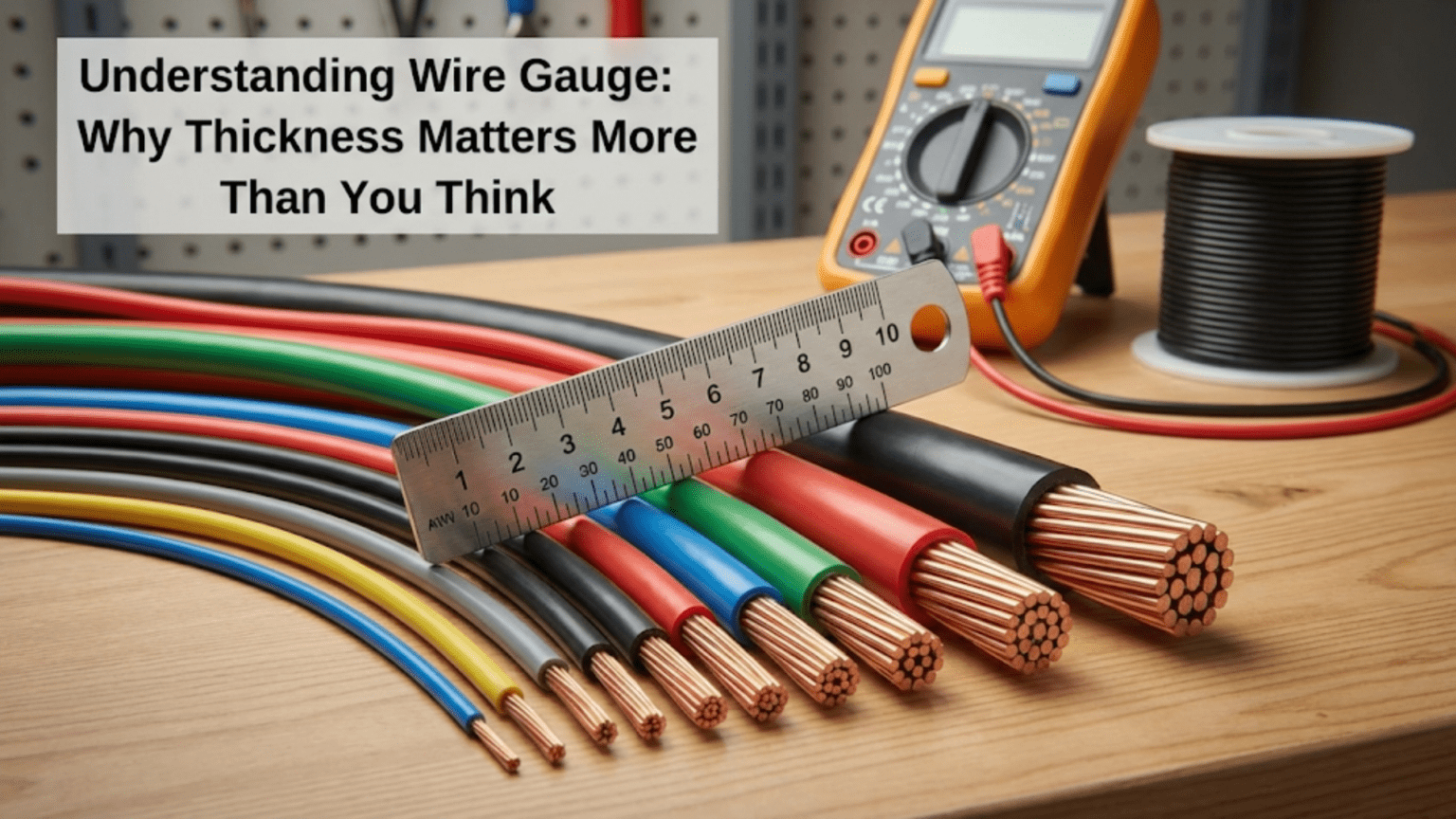
The counterintuitive aspect of wire gauge numbering confuses beginners because larger gauge numbers indicate thinner wire rather than thicker wire as you might expect. Twenty-two gauge wire is thinner than eighteen gauge wire, which is thinner than fourteen gauge wire. This backwards-seeming numbering comes from historical manufacturing processes where gauge number indicated how many drawing operations were required to reduce wire to its final diameter, with more drawing operations producing thinner wire and thus higher gauge numbers. Once you internalize this inverse relationship where higher numbers mean thinner wire and lower numbers mean thicker wire, gauge numbers become a useful shorthand for wire thickness enabling quick identification of appropriate wire sizes for different applications.
The practical implications of wire gauge affect every aspect of electronics work from breadboard jumper wires that must fit breadboard holes while providing reliable connections, through power supply wiring that must carry substantial current without excessive voltage drop or heating, to signal wiring where wire capacitance and inductance might affect high-frequency signals requiring controlled impedance. A breadboard circuit drawing one hundred milliamps works perfectly fine with thin twenty-four or twenty-six gauge jumper wire that fits breadboard holes easily, but the same circuit powered by a twelve-volt supply twenty feet away through thin wire would experience voltage drops leaving perhaps only eight or nine volts at the circuit due to resistance in the long thin wire run. Similarly, a motor drawing five amperes requires thick fourteen or sixteen gauge wire to avoid overheating and dangerous voltage drops, while the same thick wire would be unwieldy for breadboard work or connecting small components.
The safety considerations surrounding wire gauge extend beyond mere functionality because undersized wire carrying current beyond its rating generates heat through resistive power dissipation that can melt insulation, start fires, or damage components and circuit boards. The heat generated in wire equals current squared times resistance, meaning doubling current quadruples heating for a given wire size. This rapid heating escalation explains why overcurrent situations quickly become dangerous and why properly sizing wire for maximum expected current with adequate safety margin is essential rather than optional. Even if thin wire does not immediately fail when overloaded, the cumulative heating stress degrades insulation over time creating reliability problems and potential hazards that might not manifest for weeks or months after initial circuit operation.
This comprehensive guide will build your understanding of wire gauge from fundamental concepts through practical selection criteria, examining what wire gauge indicates and how gauge numbers relate to wire diameter and cross-sectional area, the American Wire Gauge standard that defines gauge sizes, how wire resistance varies with gauge affecting voltage drop and power dissipation, current-carrying capacity or ampacity for different gauges and how to select appropriate sizes, mechanical properties including flexibility and strength that vary with gauge, special considerations for different wire types including solid versus stranded wire, and practical wire selection guidelines for common electronics applications. By the end, you will understand wire gauge thoroughly enough to select appropriate wire sizes for your projects avoiding both oversizing that wastes money and space and undersizing that creates functional problems or safety hazards.
What Wire Gauge Indicates
Understanding what gauge numbers represent and how they relate to wire physical properties provides the foundation for using gauge specifications effectively.
The Inverse Relationship Between Gauge and Diameter
Wire gauge indicates wire thickness using a numbering system where higher gauge numbers represent thinner wire and lower gauge numbers represent thicker wire, creating an inverse relationship that might seem backwards initially but becomes natural with familiarity. Twenty-four gauge wire has smaller diameter than twenty-two gauge, which is thinner than twenty gauge, which is thinner than eighteen gauge. This inverse relationship means you must think in reverse when increasing or decreasing wire size, with increases in gauge number representing decreases in wire thickness.
The numerical gauge value connects to actual wire diameter through mathematical relationships defined by the American Wire Gauge standard, with each gauge increment of three corresponding to approximately doubling of wire cross-sectional area, and each increment of six corresponding to approximately doubling of wire diameter. This means eighteen gauge wire has roughly twice the cross-sectional area of twenty-one gauge wire and roughly twice the diameter of twenty-four gauge wire. These approximate doubling relationships provide useful mental shortcuts for estimating relative wire sizes without consulting tables, though precise work requires looking up exact diameters and areas for specific gauges.
The standardization of gauge numbers enables communication about wire sizes without specifying precise dimensions, with “twenty-two gauge wire” being universally understood by anyone familiar with AWG standards rather than needing to specify “zero point six four four millimeter diameter wire.” This standardization simplifies ordering wire, following circuit diagrams that specify gauge requirements, and discussing wire selection with other practitioners who share the common gauge language.
Cross-Sectional Area and Its Importance
The cross-sectional area of wire, measured perpendicular to the wire length and representing the amount of conductive material available to carry current, determines wire electrical properties more directly than diameter because area relates directly to resistance and current-carrying capacity. Larger cross-sectional area provides more parallel paths for electron flow, reducing resistance proportionally and enabling higher current capacity before heating becomes excessive. The cross-sectional area equals pi times radius squared, so area increases with the square of radius making diameter changes create proportionally larger area changes.
Wire cross-sectional area is specified in circular mils in the AWG system, where one circular mil equals the area of a circle with one-thousandth of an inch diameter. This archaic unit persists in North American wire standards despite most other measurements having transitioned to metric units, requiring familiarity with circular mil specifications when working with AWG wire. Alternatively, wire area can be specified in square millimeters using metric conventions, with conversion between units necessary when mixing standards.
The practical significance of cross-sectional area becomes apparent when calculating resistance, voltage drop, and current capacity because these all relate directly to area rather than diameter. Wire resistance per unit length is inversely proportional to area, so doubling area halves resistance. Current capacity increases approximately linearly with area, so doubling area roughly doubles safe current capacity. These direct relationships make area the fundamental wire property determining electrical performance, with gauge number merely being a convenient label corresponding to particular standardized area values.
The American Wire Gauge Standard
The American Wire Gauge system, abbreviated AWG or sometimes just gauge when context is clear, defines standardized wire sizes used throughout North America and in many other countries, particularly for electrical and electronics applications. The standard specifies exact diameters for each gauge number from 0000 gauge (read as “four-ought”) representing very thick wire used in heavy power applications through to forty gauge and beyond for very fine wire used in specialized applications. Common gauges for electronics work range from about twelve gauge for power wiring through thirty gauge or smaller for fine signal wiring and magnet wire.
The AWG standard defines not just diameter but also recommended current capacity, maximum temperature ratings, and other specifications that guide safe wire usage. These specifications assume specific installation conditions including ambient temperature, insulation type, bundling with other wires, and ventilation, so published ampacity ratings represent guidelines rather than absolute limits that apply universally regardless of conditions. Real-world wire selection must account for actual installation conditions that might reduce current capacity compared to published ratings if cooling is restricted or ambient temperature is elevated.
Different wire types within the same gauge share diameter specifications but might differ in other properties. Solid and stranded wire of the same gauge have similar cross-sectional conductor areas despite being constructed differently, with solid wire using a single continuous conductor while stranded wire uses multiple fine strands twisted together to achieve similar total area. Insulation types vary independently of gauge with different applications using rubber, PVC, Teflon, or other insulating materials selected for temperature rating, flexibility, chemical resistance, or other requirements specific to the application environment.
Wire Resistance and Voltage Drop
The resistance wire presents to current flow creates voltage drops that reduce available voltage at loads and generates heat through power dissipation, making resistance fundamental to understanding wire sizing requirements.
How Wire Resistance Varies with Gauge
Wire resistance per unit length is inversely proportional to cross-sectional area and directly proportional to length, meaning thinner wire has higher resistance than thicker wire of the same length, and longer wire runs accumulate more resistance than shorter runs of the same gauge. The resistance also depends on the conductor material, with copper having lower resistivity than aluminum making copper the standard choice for most electronics applications despite higher cost.
Standard resistance tables specify resistance per unit length for various gauges, typically given as ohms per thousand feet for AWG sizes. Twenty-four gauge copper wire has resistance around twenty-five ohms per thousand feet or approximately zero point zero two five ohms per foot, while eighteen gauge wire has resistance around six ohms per thousand feet or zero point zero zero six ohms per foot. These values show that twenty-four gauge has roughly four times the resistance of eighteen gauge per unit length, corresponding to the difference in cross-sectional area between these gauges.
Calculating total wire resistance for a circuit run requires accounting for the complete current path including both positive and return wires. A circuit with ten feet of wire from power supply to load and ten feet from load back to power supply has twenty feet of total wire in the current path. Using twenty-four gauge wire, total resistance would be twenty feet times zero point zero two five ohms per foot equals zero point five ohms. This half-ohm resistance might be negligible for low-current circuits but becomes significant when substantial current flows.
Calculating Voltage Drop from Wire Resistance
Voltage drop across wire resistance follows Ohm’s Law, with voltage drop equaling current times resistance. The half-ohm total wire resistance calculated previously creates voltage drop equal to half an ohm times current. With one hundred milliamps flowing, voltage drop is zero point five times zero point one equals zero point zero five volts or fifty millivolts—probably negligible for most circuits. With one ampere, voltage drop is zero point five volts which might be acceptable or problematic depending on circuit voltage and regulation requirements. With five amperes, voltage drop is two point five volts which is significant for any circuit voltage.
The practical impact of voltage drop manifests as reduced voltage available at loads compared to power supply output voltage. A twelve-volt power supply with zero point five ohm wire resistance and five ampere current delivers only nine point five volts to the load due to the two point five volt drop in the wire. The load receives less voltage than the power supply provides, potentially causing undervoltage operation problems if loads require close to twelve volts. Worse, variable current means voltage drop varies with load, causing supply voltage to sag when current increases and rise when current decreases, creating regulation problems.
Minimizing voltage drop requires either reducing current, reducing wire length, or increasing wire thickness to reduce resistance. For fixed current and length, the only practical option is selecting thicker wire with lower resistance. Each increment of three gauge numbers approximately halves resistance, so changing from twenty-four to twenty-one gauge wire cuts resistance in half reducing voltage drop proportionally. The trade-off is thicker wire costs more, is less flexible, and may not fit in constrained spaces requiring balance between competing requirements.
Power Dissipation and Heating in Wire
The voltage drop across wire resistance dissipates power as heat according to the power equation power equals voltage times current, which can be rewritten using Ohm’s Law as power equals current squared times resistance. This shows power dissipation increasing with the square of current, meaning doubling current quadruples heating. The heat generated must dissipate to ambient environment without raising wire temperature beyond safe limits determined by insulation material and surrounding conditions.
Excessive heating degrades insulation, eventually leading to insulation failure that exposes bare conductors creating shock hazards or short circuit risks. In extreme cases, overheating wire can ignite insulation or nearby combustible materials starting fires, explaining why wire sizing is a safety issue not merely a functional consideration. The rapid escalation of heating with increasing current makes adequate wire sizing with safety margins essential rather than merely selecting wire that barely meets minimum requirements.
Proper wire sizing ensures that heating remains well below dangerous levels even under worst-case current conditions. Standard ampacity tables provide current ratings that keep temperature rise to safe levels under typical installation conditions, though derating might be necessary for adverse conditions like high ambient temperature, poor ventilation, or bundling with many other wires that restricts cooling. Conservative wire sizing using wire gauge lower than minimum required provides safety margin accommodating unexpected current surges or installation conditions that reduce cooling below assumed values.
Current-Carrying Capacity and Wire Selection
Understanding how much current different wire gauges can safely carry guides wire selection ensuring adequate capacity without unnecessary oversizing.
Understanding Ampacity Ratings
Ampacity represents the maximum current a wire can carry continuously without exceeding its temperature rating, accounting for both heat generated by resistive power dissipation and heat removal through cooling to ambient environment. Published ampacity ratings assume specific installation conditions including thirty degree Celsius ambient temperature, free air circulation, and single isolated wire, with actual safe current capacity potentially lower if conditions reduce cooling or increase ambient temperature.
Standard ampacity tables list current capacity for various gauges, typically showing values for different insulation temperature ratings like sixty degrees, seventy-five degrees, or ninety degrees Celsius maximum conductor temperature. Higher temperature rated insulation allows higher current capacity from the same wire gauge because insulation can withstand higher temperatures without degradation. For electronics applications, conservative ratings assuming lower temperature limits provide margin for installations where cooling might be restricted.
Common electronics wire ampacity values show that twenty-four gauge wire typically handles one to two amperes safely depending on insulation type and installation conditions, twenty-two gauge handles two to three amperes, twenty gauge handles three to five amperes, and eighteen gauge handles seven to ten amperes. These values provide rough guidelines for typical work, though consulting actual ampacity tables for specific wire types and installation conditions ensures safe operation rather than relying on approximate rules of thumb.
Derating for Adverse Conditions
Published ampacity ratings assume favorable conditions that maximize cooling, but real installations often involve conditions that reduce actual safe current below published ratings. Elevated ambient temperatures reduce the temperature difference driving cooling, forcing derating to maintain safe wire temperatures. Bundling multiple current-carrying wires together creates mutual heating where heat from each wire affects others reducing individual wire current capacity. Enclosing wires in conduit or other enclosures restricts air circulation reducing cooling capability.
Derating factors account for these adverse conditions by reducing published ampacity by percentages determined from temperature rise calculations or empirical testing. A wire bundle with many conductors might require derating by thirty to fifty percent compared to single wire ratings, while elevated ambient temperature might impose additional derating. Multiple derating factors combine multiplicatively, so bundling and high temperature together create substantial capacity reductions requiring much larger wire than single wire ratings would suggest necessary.
Conservative practice involves selecting wire gauge providing comfortable margin above minimum requirements, using wire rated for at least fifty to one hundred percent more current than maximum expected under normal operation. This margin accommodates adverse installation conditions, allows for circuit modifications that increase current without requiring rewiring, and provides safety factor for unexpected current surges or fault conditions. The modest additional cost of one or two gauge sizes larger than minimum required provides excellent insurance against reliability problems and safety hazards.
Fusing and Overcurrent Protection
Wire ampacity represents continuous current capability without overheating, but actual circuits typically include fuses or circuit breakers providing overcurrent protection that limits current to safe levels preventing dangerous heating if faults create excessive current. Proper fuse selection ensures fuse rating is below wire ampacity so fuses blow before wire overheats, protecting wire and preventing fires even when faults attempt to draw current exceeding safe wire capacity.
For example, twenty-two gauge wire rated for three amperes should be protected by a fuse rated at three amperes or less, ensuring the fuse opens if current attempts to exceed wire safe capacity. Using a five-ampere fuse with three-ampere wire creates hazards because current between three and five amperes would overheat wire without blowing the fuse, potentially causing insulation failure or fires. The fuse rating must match or be lower than the weakest link in the current path, which is typically the wire unless other components have lower ratings.
The coordination between wire gauge and fuse rating ensures that overcurrent conditions blow fuses before causing wire damage, providing fail-safe operation where faults automatically disconnect power preventing hazards. This protective approach is fundamental to electrical safety and applies equally whether working with household line voltage or low-voltage electronics projects where fire hazards and insulation damage can occur even at twelve or twenty-four volts if current becomes excessive.
Solid Versus Stranded Wire
Wire construction affects mechanical properties, flexibility, and appropriate applications, with solid and stranded constructions each offering distinct advantages for different uses.
Solid Wire Construction and Properties
Solid wire uses a single continuous conductor for the entire length, creating simple robust construction that provides consistent cross-sectional area and electrical properties along the wire. The single conductor means solid wire has slightly lower resistance than equivalent stranded wire because there are no gaps between strands reducing effective conductor area, though the difference is typically negligible for practical purposes. Solid wire is less expensive to manufacture than stranded wire of similar gauge, providing cost advantages for applications where solid wire’s properties are acceptable.
The rigid nature of solid wire makes it hold its shape when bent, providing advantages for breadboard work where wire needs to span between holes while staying in position, or for circuit board assembly where component leads maintain position during soldering. However, this rigidity makes solid wire susceptible to work hardening and breakage if flexed repeatedly, limiting its usefulness for applications involving movement or vibration. Solid wire also requires larger bending radii to avoid kinking or breaking, constraining routing in tight spaces.
Breadboard jumper wires typically use solid wire because the rigidity helps wires maintain position when inserted in breadboard holes and allows wires to span distances while maintaining straight paths. Component leads use solid wire for similar reasons, with the rigid leads inserting easily through circuit board holes and maintaining position during soldering. For permanent wiring in fixed installations where flexibility is unnecessary, solid wire provides economical reliable construction.
Stranded Wire Construction and Flexibility
Stranded wire uses multiple fine strands twisted together to achieve the target cross-sectional area, creating flexible construction that bends easily and withstands repeated flexing without breaking. The flexibility comes from individual strands sliding against each other during bending rather than the entire conductor deforming as a unit, distributing mechanical stress across many small elements instead of concentrating stress in a single large conductor. This construction dramatically improves flex life compared to solid wire, with quality stranded wire enduring thousands or millions of flex cycles where equivalent solid wire might fail after tens or hundreds of cycles.
The fine strands in stranded wire require special termination techniques to prevent individual strands from separating or protruding creating short circuit hazards or intermittent connections. Soldering stranded wire requires melting solder into the twisted strands creating mechanical cohesion and electrical connection between strands, or using crimped terminals that compress strands together providing gas-tight contact without solder. For breadboard insertion, stranded wire ends can be tinned with solder creating solid tips that insert into breadboard holes more reliably than untinned stranded wire where individual strands might separate.
Applications involving movement, vibration, or repeated flexing use stranded wire because solid wire would quickly fail from fatigue. Flexible cables, movable connections, and any wiring subject to mechanical stress benefit from stranded construction providing flexibility and durability. The trade-off is slightly higher cost and more demanding termination compared to solid wire, justified when flexibility is necessary or when repeated flexing is expected.
Practical Wire Selection Guidelines
Applying wire gauge knowledge to common electronics situations requires balancing electrical requirements, mechanical considerations, and practical constraints.
Breadboard and Prototyping Wire
Breadboard work typically uses twenty-two or twenty-four gauge solid wire providing good balance between fitting breadboard holes easily while carrying adequate current for typical prototyping circuits drawing milliamps to perhaps an ampere. Twenty-two gauge fits standard breadboard holes comfortably while accommodating several insertions and removals without degrading breadboard contacts, and carries sufficient current for most prototype circuits. Twenty-four gauge provides slightly easier insertion and more flexibility for tight routing while still handling hundreds of milliamps safely.
Pre-cut jumper wire kits in standard lengths simplify breadboard construction compared to cutting and stripping custom lengths from bulk wire, though at higher cost per connection. The convenience of grab-and-go jumpers in common lengths often justifies the premium especially for beginners who find wire preparation tedious or error-prone. Buying jumper kits in multiple colors enables color coding power, ground, and signal connections improving visual circuit tracing and reducing wiring errors.
For circuits exceeding one ampere on breadboards, use eighteen or twenty gauge wire for high-current paths while using standard twenty-two or twenty-four gauge for low-current signals. This mixed gauge approach optimizes each connection for its specific current requirement rather than using oversized wire everywhere or undersizing high-current connections.
Power Supply Wiring
Power supply wiring carrying substantial current requires thicker wire to minimize voltage drop and prevent overheating, with gauge selection based on current magnitude and wire length. For short runs under a few feet and currents under one ampere, twenty or twenty-two gauge wire suffices. For currents from one to three amperes and moderate distances, eighteen gauge wire provides adequate capacity. For currents above three amperes or longer distances, sixteen or fourteen gauge wire prevents excessive drop.
Calculate voltage drop for specific applications using wire resistance tables and expected current, verifying drop remains below acceptable limits typically one or two percent of supply voltage for good regulation. If calculated drop exceeds acceptable limits, use thicker wire or shorten wire runs reducing total resistance. For critical applications where tight voltage regulation is essential, design for less than half a volt drop even if this requires quite thick wire.
Remember that current path includes both positive and negative wires, so total wire length for voltage drop calculations is twice the one-way distance from supply to load. A circuit with ten feet of separation requires twenty feet of wire in the complete current path, doubling resistance and voltage drop compared to using just ten feet of total wire length.
Signal and Sensor Wiring
Low-current signal wiring can use thin wire like twenty-four to thirty gauge where current capacity is irrelevant and mechanical flexibility or space constraints favor thin wire. However, very long signal runs might require thicker wire than current capacity alone suggests because thin wire’s high resistance creates voltage drops from even small signal currents, or because wire capacitance and inductance affect high-frequency signals requiring controlled impedance.
Shielded wire with external braided shield surrounding signal conductors prevents electromagnetic interference from coupling into sensitive signals, particularly important for low-level analog signals or high-frequency digital signals susceptible to noise. The shield connects to ground providing low-impedance path for induced currents preventing interference from affecting signal conductors.
Conclusion: Wire Gauge as Foundation for Reliable Circuits
Understanding wire gauge thoroughly enables selecting appropriate wire sizes that ensure circuits receive adequate power without voltage drops that degrade operation, while preventing overheating that creates safety hazards or reliability problems through insulation degradation. The inverse relationship between gauge numbers and wire thickness becomes natural with practice, with higher gauge numbers indicating thinner wire and lower numbers indicating thicker wire despite initial counterintuitive feelings about this numbering convention.
Wire electrical properties including resistance per unit length and current-carrying capacity scale with cross-sectional area, making area the fundamental property determining electrical performance even though gauge numbers provide convenient standard labels. Calculating voltage drop from wire resistance and current enables predicting whether wire selection maintains adequate voltage at loads, while understanding ampacity ensures wire can safely carry required current without overheating.
The distinction between solid and stranded wire affects mechanical properties and appropriate applications, with solid wire providing economical rigid construction suitable for fixed installations and breadboard work, while stranded wire provides flexibility necessary for applications involving movement or repeated flexing. Proper termination techniques adapted to construction type ensure reliable connections.
Practical wire selection balances electrical requirements against mechanical constraints and cost considerations, using appropriately sized wire for each application rather than defaulting to arbitrary sizes. Conservative sizing providing margin above minimum requirements accommodates adverse conditions and circuit modifications while improving safety and reliability with minimal additional cost.