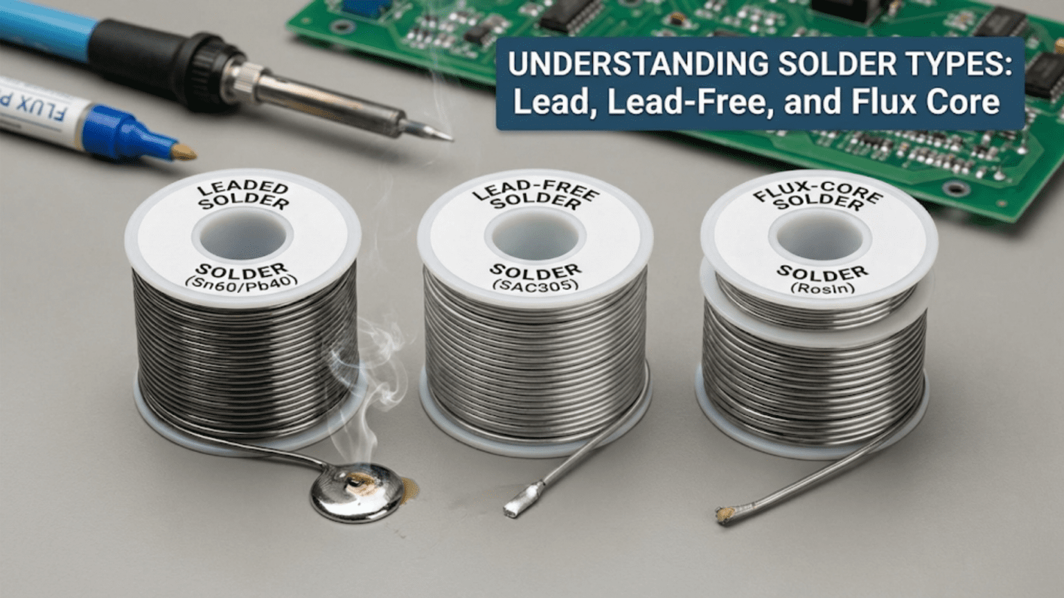
Solder used in electronics falls into two primary categories: leaded solder (typically 60/40 or 63/37 tin-lead alloy, melting at 183–190°C) and lead-free solder (most commonly SAC305 at 96.5% tin, 3% silver, 0.5% copper, melting at 217–220°C). Both types are available as flux-core wire, which contains a hollow channel filled with flux that activates during soldering to clean oxide layers and improve wetting. Leaded solder is easier to work with and produces shiny joints, while lead-free solder is required for most commercial electronics under RoHS regulations but demands higher temperatures, better technique, and produces slightly matte joints that are normal and not indicative of defects.
Introduction: Why Solder Type Matters More Than You Think
Walk into any electronics supply store and you’ll find shelves lined with different spools of solder wire—various alloy compositions, different wire diameters, multiple flux types, various brands promising different properties. To a beginner, the choice can seem arbitrary. Does it really matter which solder you use? Can’t you just grab whatever’s available and get to work?
The answer is that solder choice matters considerably—sometimes critically. The alloy composition determines the melting temperature and working range, which in turn determines what iron temperature you need, how much time you have before the joint solidifies, and how forgiving the material is to technique errors. The flux type affects how aggressively oxidation is removed, what residue remains after soldering, whether that residue needs cleaning, and whether the joint will be reliably made on oxidized or difficult surfaces. The wire diameter controls how precisely you can deposit solder and how much material flows per inch of feed. Even the solder’s thermal and mechanical properties after solidification affect how joints behave under stress and temperature cycling.
These aren’t just academic concerns. A hobbyist building a one-off prototype can use whatever solder is convenient with minimal consequence. But someone designing a product that must survive automotive temperatures, a technician repairing a safety-critical medical device, or an engineer qualifying a manufacturing process needs to understand exactly what each solder type offers and what trade-offs it involves.
Even for hobbyists, understanding solder types helps you make better choices: why the leaded solder you used for years makes beautiful shiny joints while the lead-free reel you received in a kit produces dull-looking (but perfectly good) joints; why you struggle to solder old components that solder well with extra flux; why some solders seem to produce more bridges on fine-pitch work; and why the “same temperature” setting on your iron works better with one solder than another.
This comprehensive guide explores the full landscape of solder types used in electronics. We’ll examine the metallurgy of each alloy type, understand the physical reasons behind different working characteristics, explore flux types and their roles, learn how to choose the right solder for different applications, and develop a practical understanding of how solder choice affects everything from technique to joint reliability.
The Metallurgy of Solder: Why Alloy Composition Matters
What Makes a Good Electronics Solder
Not every metal alloy can serve as electronics solder. An ideal electronics solder must:
- Melt at a safe temperature: Hot enough to ensure complete fusion, but not so hot that it damages PCB substrates (typically FR4, which degrades above 130–170°C sustained), component packages, or insulating materials
- Wet metals used in electronics: Primarily copper (PCB pads and traces), tinned copper (component leads), nickel, gold, and silver finishes
- Form reliable intermetallic bonds: Chemical bonds at the interface that create strong, durable connections
- Solidify predictably: Ideally with a sharp melting point (eutectic) or a narrow mushy zone to minimize disturbed joint risk
- Conduct electricity: Low electrical resistivity
- Resist thermal and mechanical fatigue: Joints survive thousands of temperature cycles and mechanical stresses over product lifetime
- Be manufacturable: Available in reliable alloy consistency, appropriate wire forms, and reasonable cost
Tin forms the basis of virtually all modern electronics solders because it wets copper exceptionally well, forms reliable intermetallic bonds, and has appropriate physical properties. The question is what other metals are added to optimize the blend.
Phase Diagrams and Melting Behavior
Understanding how solder alloys melt requires a brief introduction to phase diagrams—a concept that sounds intimidating but has very practical implications.
Eutectic composition: When two metals are combined at a specific ratio, the mixture may melt at a single temperature (lower than either pure metal’s melting point), behaving like a pure substance with a sharp solid-to-liquid transition. This special composition is called the eutectic point.
Why eutectic matters for soldering: A eutectic solder transitions directly from solid to fully liquid with no intermediate “pasty” phase. This means:
- Solder solidifies quickly and completely once cooled
- Less risk of disturbed joints (no pasty phase to disturb)
- More predictable process window
Non-eutectic alloys: Most solder compositions are slightly off eutectic, meaning they have a “mushy zone”—a temperature range where solid and liquid coexist. During this pasty phase, the joint looks solid but isn’t—movement creates disturbed joints.
Practical implication: Eutectic 63/37 tin-lead solder (eutectic at exactly 183°C) is easier to use correctly than 60/40 (which has a small mushy zone). Similarly, certain lead-free alloys are more forgiving because they have narrower mushy zones.
Leaded Solder: The Traditional Standard
60/40 Tin-Lead Solder
Composition: 60% tin (Sn), 40% lead (Pb)
Melting range: 183–190°C (solidus at 183°C, liquidus at 190°C)
Mushy zone: 7°C (small but present)
Typical working temperature: 315–340°C iron temperature
Appearance of good joint: Bright, shiny, mirror-like surface
Key properties:
- Excellent wetting: Flows readily onto copper and common PCB finishes
- Good surface tension: Holds appropriate fillet shape
- Forgiving technique: Small errors still produce acceptable joints
- Easy to rework: Flows readily at modest temperatures
- Clear visual indicator: Shiny = good, dull = cold joint (straightforward inspection)
Limitations:
- Contains lead (hazardous material, regulated for commercial use)
- Higher melting point solder produces stronger joints over long term
- Slightly creep-susceptible over time (lead undergoes slow plastic deformation)
Best for:
- Hobby electronics and prototype work
- Repair and rework of existing leaded assemblies
- Learning to solder (much more forgiving than lead-free)
- Any application exempt from RoHS restrictions
63/37 Tin-Lead Eutectic Solder
Composition: 63% tin (Sn), 37% lead (Pb) — the eutectic composition
Melting point: Exactly 183°C (eutectic — no mushy zone)
Typical working temperature: 315–340°C
Appearance of good joint: Bright, shiny (same as 60/40)
Advantage over 60/40: The eutectic composition means solder transitions sharply from liquid to solid. There is no pasty phase. This makes disturbed joints less likely during cooling and gives the solder a slightly crisper working feel.
When to choose 63/37 over 60/40:
- Precision work where disturbed joints are a concern
- Hand soldering fine-pitch components
- Any situation where you want the most predictable solidification
Trade-off: 63/37 is slightly more expensive due to higher tin content. Performance difference is minor for most hobby work; significant for professional precision assembly.
Other Leaded Alloys
62/36/2 (Sn/Pb/Ag): Small addition of silver improves mechanical strength and creates stronger bonds to silver-metalized surfaces. Used in some professional applications, particularly for components with silver-plated leads.
50/50 (Sn/Pb): Older formulation with higher lead content. Higher melting point than 60/40. Was used in plumbing and some industrial applications. Rarely seen in electronics today.
10/90 (Sn/Pb): Very high lead content, very high melting point (~275–302°C). Used for step soldering (joining assemblies that will be exposed to subsequent soldering operations — the high-temperature solder doesn’t reflow when lower-temperature solder is applied nearby).
Lead-Free Solder: The Modern Standard
Why Lead-Free?
The shift to lead-free solder was driven primarily by environmental and health legislation:
RoHS (Restriction of Hazardous Substances) Directive: The European Union’s RoHS directive, effective July 2006, restricts lead in electronic and electrical equipment sold in the EU. Similar legislation followed in China, Japan, South Korea, and many other jurisdictions.
Environmental concerns: Lead is a persistent toxic heavy metal. Electronic waste (e-waste) in landfills leaches lead into groundwater. Manufacturing workers, recyclers, and communities near e-waste sites face elevated lead exposure risks.
The challenge: Lead was part of solder because it genuinely improves the material’s soldering characteristics. Its removal required developing alloys that could match lead-solder’s performance without containing lead—a significant materials science challenge. No single alloy perfectly replaces tin-lead; instead, different alloys excel in different application areas.
SAC305: The Industry Standard
Composition: 96.5% tin (Sn), 3.0% silver (Ag), 0.5% copper (Cu)
Melting range: 217–220°C (near-eutectic, very narrow mushy zone)
Typical working temperature: 350–380°C iron temperature
Appearance of good joint: Slightly matte, somewhat grainy — this is NORMAL and does NOT indicate a cold joint
Why SAC305 dominates: After extensive industry research, SAC305 emerged as the best all-around compromise for reflow (oven) soldering of consumer and commercial electronics. It offers:
- Excellent reliability under thermal cycling
- Good wetting on common PCB finishes
- Reasonable silver content (improves joint quality without excessive cost)
- Near-eutectic behavior (narrow mushy zone)
- Strong track record across billions of production units
The appearance issue: Perhaps the most important thing to understand about SAC305 and most lead-free solders is that a slightly matte, slightly grainy appearance is normal and does not indicate a defect. This confuses many people accustomed to leaded solder, where dullness always meant a cold joint. Lead-free joints look different because the tin-silver-copper microstructure reflects light differently than tin-lead. A good lead-free joint is smooth, well-formed, and has good coverage—it just won’t be mirror-bright.
Limitations of SAC305:
- Higher melting point demands higher iron temperatures and more heat in the joint
- Less forgiving of technique errors (narrower process window)
- Less flux wetting than 60/40 (surface tension higher, requires better flux)
- Silver content makes it more expensive than pure tin-copper alternatives
- Requires higher soldering iron quality (temperature-controlled stations essential)
SN100C (Sn/Cu/Ni/Ge)
Composition: ~99.3% tin (Sn), ~0.7% copper (Cu), trace nickel (Ni) and germanium (Ge)
Melting range: 227°C (higher than SAC305)
Best applications: Wave soldering in production environments
Why the trace elements matter:
- Nickel (Ni) reduces copper dissolution rate (PCB pads and copper in the solder bath erode more slowly)
- Germanium (Ge) reduces oxidation and improves surface quality
For hand soldering: SAC305 is generally preferred over SN100C due to lower melting point and better hand soldering characteristics.
Sn96.5/Ag3.5 (Two-Component Silver-Tin)
Composition: 96.5% tin, 3.5% silver — near eutectic
Melting point: 221°C (near eutectic point of Sn-Ag system)
Properties:
- Good mechanical properties
- Higher silver content than SAC305 (slightly more expensive)
- Somewhat better wetting than SAC305 in some scenarios
Use case: Hand soldering, rework, and applications where SAC305 isn’t available
Bismuth-Containing Alloys (Low-Temperature Lead-Free)
Compositions:
- Sn/Bi (Tin-Bismuth): Various ratios, melting as low as 138°C for eutectic 58/42 Bi/Sn
- Sn/Bi/Ag: Tri-metal alloys with intermediate properties
Why use low-temperature lead-free?
- Heat-sensitive components (OLED displays, certain LEDs, flex circuits)
- Rework without reflowing nearby joints
- Reduced thermal stress on PCBs and components
Important concern — silver and bismuth interaction: Bismuth-containing solders should NOT be used on silver-plated surfaces or mixed with SAC305 (which contains silver). Bismuth-silver intermetallics at grain boundaries are extremely brittle and can cause catastrophic joint failure. Always check surface finishes before using bismuth solders.
Indium-containing alloys: Indium is sometimes added to tin-bismuth to address the brittleness concern and improve low-temperature solder reliability. These alloys are expensive but used in specialized applications.
Comparison: Choosing Between Lead and Lead-Free
Use leaded solder when:
- You’re learning to solder (far more forgiving)
- Your application is exempt from RoHS (hobby, repair, military, medical)
- You’re repairing or reworking existing leaded assemblies (mixing is generally acceptable with care)
- Maximum reworkability and lowest defect rate is the priority
Use lead-free solder when:
- Your product must comply with RoHS or similar regulations
- Building products for sale in regulated markets
- Long-term environmental responsibility is a priority
- Your temperature-controlled soldering station can reliably reach 370–400°C
Never mix freely: While small amounts of leaded solder in a lead-free assembly (or vice versa) are unlikely to cause catastrophic failure, mixing changes the alloy composition and melting characteristics unpredictably. In professional settings, mixing is strictly avoided. In hobby work, occasional cross-contamination during rework is usually inconsequential.
Flux: The Hidden Ingredient
What Flux Does: A Deeper Look
Flux is not simply a “helper”—it is chemically essential to soldering. Without flux, reliable solder joints are physically impossible because:
Oxide chemistry: Copper oxidizes extremely rapidly. At room temperature, exposed copper forms an oxide layer within seconds. At soldering temperatures (300°C+), oxidation is near-instantaneous. Tin in solder also oxidizes. Oxide layers are:
- Not wettable by molten solder
- Poor electrical conductors
- Physical barriers preventing metal-to-metal contact needed for intermetallic bonding
What flux does chemically: Flux contains organic acids or other reactive compounds that dissolve metal oxides:
Cu₂O + 2RCO₂H → 2CuOCOR + H₂O
(Copper oxide + organic acid → copper salt + water)
This reaction removes the oxide layer, exposing clean metal that solder can wet. Flux continues reacting during the soldering process, preventing re-oxidation as long as it remains active.
Secondary effects:
- Reduces surface tension of molten solder, improving flow and wetting
- Transfers heat more efficiently from iron tip to joint
- Helps solder fill small gaps and through-holes
Flux Classifications: The IPC System
The electronics industry classifies flux using the IPC (Association Connecting Electronics Industries) system based on flux base and activity level:
Rosin-based flux (R, RA, RMA, RSA): Natural pine resin-derived flux, the traditional electronics flux standard.
- R (Rosin): Plain rosin, mildest activity. Leaves clear, non-conductive residue. Rarely sufficient alone for anything but freshest components.
- RA (Rosin Activated): Activating agents added. More effective on mildly oxidized surfaces. Classic electronics flux. Leaves removable rosin residue.
- RMA (Rosin Mildly Activated): Balance between effectiveness and residue safety. The workhorse of electronics hand soldering for decades. Residue is generally non-corrosive but may need removal in sensitive circuits.
- RSA (Rosin Strongly Activated): Highest activity rosin flux. Used for difficult-to-solder surfaces. Residue must be thoroughly cleaned.
No-clean flux (NC): Formulated so that residue remaining after soldering is electrically inert and non-corrosive, eliminating the cleaning step.
- Very popular in production soldering for cost savings
- Residue is white or light-colored, sometimes slightly waxy
- Most hobby solder wire uses no-clean flux
- Still best to clean before conformal coating or for precision/high-frequency circuits
Water-soluble flux (OA, Organic Acid): Highly active organic acid flux that aggressively removes oxides.
- Most effective for heavily oxidized surfaces
- Must be completely removed with deionized water within hours — residue is corrosive
- Not typically used in hand soldering; more common in wave soldering
Synthetic flux: Synthetic resin or other non-rosin base with various activity levels. Similar classification system to rosin types.
Flux in Solder Wire: The Core
Modern electronics solder wire contains flux embedded inside as one or more hollow channels running through the wire’s core. This “flux-core” design was developed to provide flux precisely where and when it’s needed during hand soldering.
Single-core vs. multi-core:
- Single-core: One flux channel, simpler manufacturing
- Multi-core (2%, 3%, 5% flux by weight): Multiple channels for more uniform flux distribution; popular in professional solder
Flux percentage matters:
- Lower flux content (1–2%): Suitable for clean surfaces, produces less residue
- Higher flux content (3–4%+): Better for older or mildly oxidized components, more forgiving
What “% flux” means on solder packaging: The percentage refers to flux by weight in the wire. A spool labeled “2% flux core” contains 2 grams of flux per 100 grams of solder wire.
External Flux: When to Add More
Flux-core solder contains just enough flux for ideal conditions. Many situations benefit from additional flux applied separately:
When to add external flux:
- Reworking or desoldering existing joints (original flux has burned off)
- Soldering old or oxidized components (heavy oxide load exceeds flux-core capacity)
- Fine-pitch SMD work where additional flow improvement helps
- Drag soldering techniques
- Any joint that isn’t flowing well despite correct temperature and technique
- Soldering to unusual metals (aluminum, stainless steel — requires special flux)
Forms of external flux:
- Flux pens: Felt-tip pen filled with liquid flux. Precise, convenient, popular for rework
- Flux paste (gel): Thick paste in a syringe. Used for SMD work; holds components in place
- Liquid flux in a bottle: Applied with a brush; economical for frequent use
- No-clean flux in all forms: Leaves benign residue; recommended for most hand soldering rework
Wire Diameter and Form Factors
Choosing Wire Diameter
Solder wire diameter directly controls how much solder is deposited per unit length fed into the joint.
Common diameters and applications:
0.3–0.4mm (very fine):
- Ultra-fine pitch SMD work (0.4mm pin pitch ICs, 0201 chip components)
- Maximum precision, minimum solder per contact
- Requires careful feed control
- Rarely needed for hobby work
0.5–0.6mm (fine):
- Fine-pitch SMD work (0.5–0.8mm pitch)
- Small through-hole components
- Good all-around choice for mixed work
- Recommended for hobbyists who do some SMD work
0.7–0.8mm (standard):
- Standard through-hole components
- General electronics assembly
- Best general-purpose choice for most hobbyists
- Good balance of control and speed
1.0mm (medium):
- Larger through-hole components
- Connectors with substantial pins
- Some power work
1.5–2.0mm (heavy):
- Large terminal lugs, heavy connectors
- Power electronics, chassis grounding
- Not suitable for precision PCB work
Practical advice: Most hobbyists can cover 90% of their work with 0.6–0.8mm wire. If you do any SMD work, having 0.5mm available as well is beneficial. Avoid very thick wire (1.5mm+) for PCB work — you’ll deposit too much solder with each touch.
Solder Bar and Paste
While wire is the primary form for hand soldering, other forms are used in production:
Solder bar: Used in wave soldering machines and solder pots for dip soldering. Bars are melted into a bath that PCBs pass through, soldering all through-hole components simultaneously.
Solder paste: A mixture of microscopic solder powder and flux in a sticky paste. Applied to PCB pads by stencil printing, components are placed (held by paste’s stickiness), then the entire assembly passes through a reflow oven. Essential for surface-mount assembly.
Solder preforms: Pre-formed pieces of solder (washers, rings, discs) used for specific applications where consistent solder volume is required.
Specialty Solder Types
Silver-Bearing Solders
Several lead-free alloys contain elevated silver content beyond SAC305’s 3%:
Higher silver content provides:
- Improved joint strength and creep resistance
- Better reliability under thermal cycling in some applications
- Improved wetting on silver-plated surfaces
Common application: High-reliability joints in aerospace, medical, and industrial applications.
Cost consideration: Silver is expensive; higher silver content means significantly higher solder cost.
Indium-Containing Solders
Indium improves low-temperature solder properties and adds unique characteristics:
Sn/In alloys:
- Very low melting points achievable (down to 117°C for 52% indium eutectic)
- Excellent for heat-sensitive assemblies
- Indium is expensive; these solders are specialty items
Indium/Bismuth: Addresses bismuth brittleness at grain boundaries, enabling more reliable low-temperature joints.
Specialty High-Temperature Solders
For step-soldering applications or high-temperature environments:
Au/Sn (Gold-Tin, 80/20):
- Melting point: 280°C
- Used in optoelectronics, hermetic sealing, and high-reliability applications
- Very expensive
Pb/Sn high-lead alloys:
- Specifically exempted from RoHS for high-reliability applications
- Used in aerospace, military, and medical devices where reliability outweighs environmental concerns
- Higher melting points than standard 60/40
Conductive Adhesives (Not True Solder)
Electrically conductive adhesives fill some roles that solder traditionally served:
Silver-loaded epoxy:
- Cures at room temperature or low temperature
- Used on heat-sensitive substrates, some flexible electronics
- Higher resistance than solder
- Not reworkable (epoxy is permanent)
Isotropic Conductive Adhesive (ICA): Conducts in all directions — used for general bonding
Anisotropic Conductive Adhesive (ACA/ACF): Conducts only in one direction — used in display connections
Comparison Table: Solder Types for Electronics
| Property | 60/40 Sn/Pb | 63/37 Sn/Pb (Eutectic) | SAC305 | Sn/Bi (Low-Temp) | No-Clean Flux Core |
|---|---|---|---|---|---|
| Tin content | 60% | 63% | 96.5% | ~42% Sn, 58% Bi | Depends on alloy |
| Melting range | 183–190°C | 183°C exact | 217–220°C | 138°C (eutectic) | Depends on alloy |
| Working temp (iron) | 315–355°C | 315–350°C | 350–385°C | 250–300°C | Same as base alloy |
| Joint appearance | Shiny/mirror | Shiny/mirror | Slightly matte | Slightly matte | Same as base alloy |
| Wetting quality | Excellent | Excellent | Good | Moderate | Same as base alloy |
| Technique forgiveness | High | High | Moderate | Moderate | Same as base alloy |
| RoHS compliant | No | No | Yes | Yes (check Bi rules) | Depends on alloy |
| Relative cost | Low | Low | Moderate | Moderate–High | Adds slight cost |
| Residue cleanup | Recommended | Recommended | Optional (NC flux) | Recommended | Not required (NC) |
| Best application | Hobby, repair | Precision hobby | Commercial products | Heat-sensitive work | General use |
| Availability | Common | Common | Very common | Specialty | Universal |
| Cold joint detection | Easy (shiny vs dull) | Easy (shiny vs dull) | Harder (both may look matte) | Moderate | Same as base alloy |
Practical Selection Guide
For Complete Beginners
Recommendation: 60/40 or 63/37 leaded solder, 0.6–0.8mm diameter, RMA or no-clean flux core
Why:
- Most forgiving alloy type to work with
- Clear visual feedback (shiny = good)
- Lower working temperature (easier on components while learning)
- Widely available at reasonable cost
If leaded solder is unavailable or you prefer lead-free from the start: use SAC305 with a quality temperature-controlled iron, set to 370°C, and add extra flux to compensate for reduced wetting.
For General Hobby Use
Recommendation: SAC305 or 63/37, 0.6–0.8mm, no-clean flux core
Either alloy works well for most hobby applications. If building products to sell or share, use lead-free (SAC305). For personal use, either is appropriate.
For Commercial/Production Work
Required: Lead-free per RoHS — SAC305 is the standard
Use temperature-controlled reflow for SMD, hand soldering for connectors and through-hole. Select flux type based on your cleaning process (no-clean if no cleaning step, water-soluble if thorough cleaning is feasible).
For Repair and Rework
Match the existing solder on the board when possible
- Repairing an old leaded-solder board: Use leaded solder
- Repairing a lead-free board: Ideally use SAC305; occasional use of leaded solder for rework is generally tolerated but introduces alloy mixing
- Always add extra flux during rework — the original flux has long since burned off
For Fine-Pitch SMD Work
Recommendation: SAC305 or 63/37, 0.4–0.5mm diameter, flux pen for additional flux
Fine wire gives precise control. External flux dramatically improves fine-pitch results.
Storage and Handling
Proper Solder Storage
Solder wire has a shelf life that varies by alloy and flux type:
Leaded solder: Very stable; can last 10+ years if stored properly. Lead doesn’t corrode significantly under normal storage conditions.
Lead-free solder: Tin-rich alloys are susceptible to tin whisker growth over decades and slight surface oxidation. Still perfectly usable for many years under proper conditions.
Flux-core solder: The flux is the most sensitive component. Flux can degrade or dry out if exposed to heat, humidity, or air over time. Degraded flux core produces solder that doesn’t wet well—old solder that performs poorly is usually a flux problem, not an alloy problem.
Proper storage conditions:
- Cool, dry environment (below 25°C, below 50% relative humidity)
- Sealed bag or container when not in use
- Away from direct sunlight and heat sources
- Original packaging or airtight container
Signs of degraded solder:
- Wire takes excessive temperature or contact time to flow
- Joints wet poorly despite correct technique
- Flux “spits” or sputters excessively when heated
- Residue is heavier or darker than usual
Safety Handling
Lead (in leaded solder): Lead is absorbed through ingestion, not through skin contact with solder wire under normal handling. Nevertheless:
- Wash hands before eating, drinking, or touching face
- Don’t eat or drink at the soldering bench
- Keep the workspace clean of solder scraps and dust
- Dispose of used solder, trimmings, and contaminated materials properly
Lead-free solder: Still contains tin and possibly silver, copper, bismuth. Less hazardous than leaded, but same hygiene practices apply.
Flux fumes: Flux fumes from any solder type are respiratory irritants. Work in ventilated areas or use a fume extractor. No-clean fluxes at appropriate temperatures produce less irritating fumes than highly activated fluxes at excessive temperatures.
Conclusion: Choosing Solder With Confidence
Solder selection is not a deep mystery, but it does reward understanding. The major decision—leaded versus lead-free—is usually determined by regulatory requirements and personal philosophy. The secondary decisions—specific alloy, wire diameter, flux type—are guided by the specific application and personal working style.
The Most Important Points
For beginners: Leaded 60/40 or 63/37 is simply easier to use. It’s more forgiving, provides clear visual feedback, and produces reliable joints with less precise technique. If you’re learning, start with leaded unless regulatory or ethical concerns prevent it.
For commercial work: SAC305 is the industry standard for a reason—it represents the best overall balance of properties for reflow and hand soldering in regulated applications. Learn it properly (higher temperature, more flux, accept matte appearance) and it produces excellent results.
Flux matters as much as alloy: The alloy is the joining metal; the flux makes the wetting possible. Fresh, active flux—whether from the wire core or applied externally—is often the difference between a good joint and a frustrating one.
Appearance expectations differ: The single biggest source of confusion for people transitioning from leaded to lead-free solder is the visual difference. Lead-free joints that look matte and slightly grainy are not defective. Learn to evaluate joint quality by shape and coverage, not by shine alone.
Diameter for control: Use finer wire for finer work. A 0.6–0.8mm spool covers most through-hole work beautifully; 0.5mm or finer when SMD work requires precision.
The Bigger Picture
Solder technology continues to evolve. Low-temperature alloys are gaining ground as heat-sensitive components—especially in flexible electronics and wearables—become more common. The push for sustainability drives ongoing research into alternatives to silver (expensive) and bismuth (supply chain concerns). New flux chemistries continue to improve no-clean flux performance. Understanding the principles—wetting, intermetallics, flux chemistry, eutectic behavior—allows you to evaluate new solder products as they emerge and make informed choices rather than simply following trends.
Whether you’re soldering your first resistor or qualifying a new solder paste for a production line, the fundamentals are the same: choose the right alloy for your application, ensure adequate flux, apply sufficient heat to form proper intermetallics, and inspect the results. Do that consistently, and your solder joints will be reliable and lasting—regardless of which solder type fills your favorite spool.