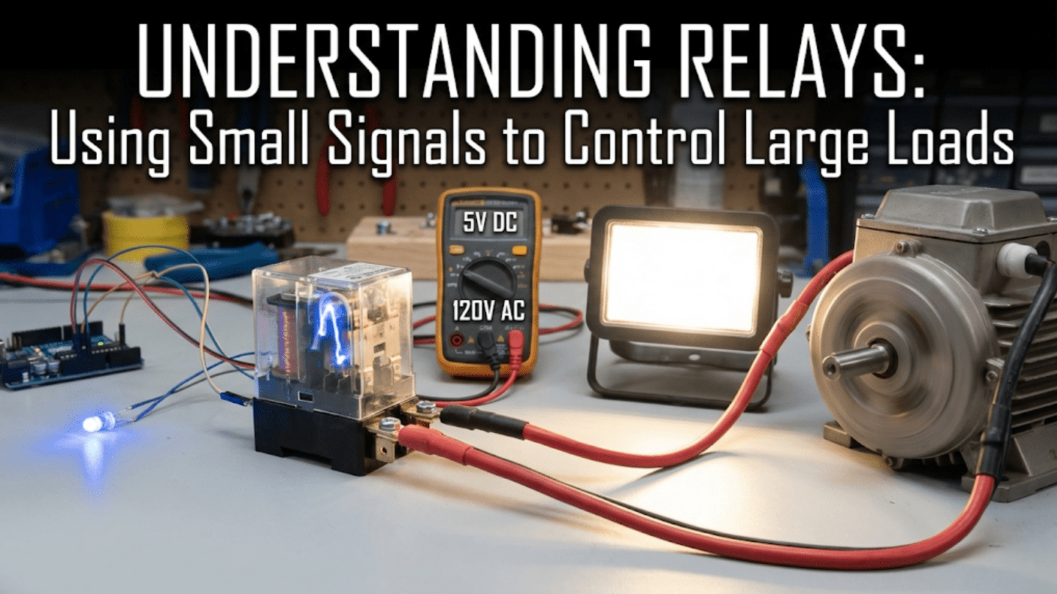
A relay is an electrically controlled mechanical switch—a small electromagnet that, when energized by a low-power control signal, pulls a movable armature to physically open or close a separate set of high-power switch contacts. This lets a 5V microcontroller output driving a few milliamps of coil current switch a 240V AC circuit carrying 10 amps or more, with complete electrical isolation between the control and load sides. The relay provides both amplification (small signal controls large power) and isolation (the control circuit has no electrical connection to the switched circuit), making it the safest and most straightforward way to interface digital electronics with mains-voltage appliances and industrial loads.
Introduction: The Bridge Between Logic and Power
Every practical automation system faces the same fundamental challenge: the digital electronics that make decisions—microcontrollers, logic ICs, sensors, computers—operate at low voltages and low currents. The physical loads those electronics need to control—lighting, motors, heating elements, appliances—often require high voltages and high currents completely incompatible with delicate semiconductor logic.
A microcontroller GPIO pin outputs perhaps 3.3V and 8mA. A household lamp draws 120V or 240V at half an amp to several amps. A motor starter may require switching several hundred volts at tens of amps. The gap between what a microcontroller produces and what these loads require is enormous—not just in voltage and current magnitude, but in the very nature of the signal: AC versus DC, mains voltage versus logic voltage, high-energy circuits versus circuits where a miswiring could destroy an IC instantly.
Relays solve this challenge elegantly, and they have been doing so for over 170 years. The first relays were invented by Joseph Henry and used by Samuel Morse in the telegraph system—when a telegraph signal grew too weak over long distances, a relay would use the weak arriving signal to energize a fresh, local battery, regenerating the signal. This basic concept—a weak signal controlling a strong one through electromagnetic action—remains the relay’s defining function today.
What makes relays particularly valuable in modern electronics is not just their switching ability, but the complete galvanic isolation they provide between the control and load sides. When a relay switches a 240V circuit, there is no electrical connection whatsoever between the mains voltage and the microcontroller. They share only a magnetic field—and magnetic fields don’t conduct electricity. This isolation is why relays remain irreplaceable despite the availability of solid-state alternatives, especially in safety-critical, industrial, and mains-connected applications.
This comprehensive guide explores relays completely: the electromagnetic mechanism that makes them work, the anatomy of relay contacts and their specifications, the types of relays for different applications, how to drive relays safely from microcontrollers, the essential protection circuits, and when to choose relays versus solid-state alternatives.
Part 1: How Relays Work — The Electromagnetic Mechanism
The Basic Structure
A mechanical relay consists of five fundamental elements:
1. Electromagnet (coil): A coil of wire wound on a ferromagnetic core. When current flows through this coil, it creates a magnetic field. The coil is specified by its operating voltage (typically 5V, 12V, or 24V DC) and the current it draws. The coil resistance determines current: I_coil = V_coil / R_coil.
2. Armature: A movable piece of ferromagnetic material (iron) positioned near the electromagnet. When the electromagnet is energized, it attracts the armature with enough force to move it against the spring.
3. Return spring: Holds the armature in its default (deenergized) position. When the coil is deenergized, the spring pulls the armature back.
4. Contacts: The actual electrical switch, mechanically connected to the armature. When the armature moves, it opens or closes these contacts. The contacts are completely separate from the coil circuit.
5. Yoke/frame: The mechanical structure supporting all components and providing the magnetic return path for the flux from the coil.
The Switching Action
Relay deenergized (coil current = 0): The spring holds the armature in its rest position. The normally closed (NC) contacts are touching (circuit through NC is closed). The normally open (NO) contacts are open (circuit through NO is open).
Relay energized (coil current flows): The magnetic field from the coil attracts the armature, pulling it toward the core against spring pressure. The armature moves, mechanically opening the NC contacts and closing the NO contacts.
The key physics: The force developed by an electromagnet is proportional to the square of the current and inversely proportional to the square of the air gap. As the armature moves closer to the core (gap decreases), the force increases rapidly—a positive feedback that snaps the relay into the fully engaged position. This snap action provides clean, fast contact closure.
Coil power: P_coil = V_coil × I_coil = V_coil² / R_coil
A typical small relay (5V coil, 72Ω resistance): I_coil = 5V / 72Ω = 69mA P_coil = 5V × 69mA = 345mW (about 0.35W) — more than most microcontroller pins can drive directly!
This is why relay driving circuits almost always include a transistor between the microcontroller and the relay coil.
Part 2: Relay Contact Terminology and Ratings
Contact Forms and Configurations
Normally Open (NO): Contact is OPEN when relay is deenergized; CLOSES when relay is energized. Like a push-button that stays open until pressed — except the relay “presses” itself when its coil is energized.
Normally Closed (NC): Contact is CLOSED when relay is deenergized; OPENS when relay is energized. The safe default — circuit stays on unless the relay is deliberately energized to break it.
Single Pole Single Throw (SPST): One movable contact, one fixed contact. Either NO or NC. Simplest form — like a single switch.
Single Pole Double Throw (SPDT): One movable contact (common), one NO contact, one NC contact. The most versatile and common relay configuration. Also called “Form C” relay.
         COM (Common)
          │
     ┌────┤
     │    │
    NC    NO
(closed  (open
when     when
off) off)Double Pole Double Throw (DPDT): Two independent SPDT switches operated simultaneously by a single coil. Allows switching two separate circuits simultaneously or provides circuit redundancy.
Multiple pole configurations: Some relays have 3, 4, or more poles — all controlled by a single coil. Used when multiple circuits must switch synchronously.
Electrical Contact Ratings
Contact voltage rating: Maximum voltage the contacts can switch. Separate ratings often given for AC and DC:
- AC rating: Usually higher (e.g., 250V AC)
- DC rating: Usually lower (e.g., 30V DC) — DC arcing is harder to extinguish than AC
Contact current rating: Maximum steady-state current through contacts. Exceeding this causes contact overheating and welding. Common ratings: 1A, 3A, 5A, 10A, 16A, 30A.
Contact resistance: Resistance of closed contacts — should be very low (milliohms). Increases with contact wear and oxidation. High contact resistance causes heating and voltage drop.
Breaking capacity: Maximum current that can be safely interrupted (switched off) — often lower than the contact current rating because breaking current generates an arc. For inductive loads (motors, solenoids), the breaking capacity may be significantly derated because of inductive voltage spikes during current interruption.
Load types affect relay life:
- Resistive loads (heaters, incandescent lamps when fully on): Rated current is straightforward
- Motor loads: High inrush current at startup (3–10× running current); requires derating
- Incandescent lamp loads: Cold filament has very low resistance — inrush current 5–15× steady state; use a relay rated for lamp loads
- Inductive loads (motors, solenoids, coils): Generate voltage spikes when switched off; use snubber circuits or relays rated for inductive loads
Mechanical Life vs. Electrical Life
Relays have two distinct life ratings:
Mechanical life: Operations without load (no current through contacts). Typically 10 million to 100 million operations. The mechanical parts simply cycle open and closed.
Electrical life: Operations with rated load. Dramatically lower — typically 100,000 to 1 million operations. Contact arcing during switching erodes contact material over time.
Example: A relay rated for 10 million mechanical operations / 100,000 electrical operations at rated load:
- If switching twice per hour: 100,000 / (2 × 24 × 365) = 5.7 years at rated load
- If the actual load is 20% of rated: Life extends dramatically (arcing intensity falls with current)
For high-cycle applications (relays switching many times per hour), contact life is the primary selection criterion.
Part 3: Relay Types
General Purpose (Power) Relays
The most common type for electronics projects and industrial control:
Package: Through-hole PCB mount (solder pins), panel mount, or DIN rail mount Coil voltage: 5V, 12V, 24V DC most common; also 24V AC, 48V AC, 120V AC Contact rating: 1A to 30A, 120V/240V AC or 30V/60V DC typical Size: From fingernail-sized PCB relay to industrial panel relay
Examples:
- Omron G5V-2: Small PCB relay, 5V coil, 1A contacts — suitable for signal switching
- Omron G5LE: Medium PCB relay, 5V/12V coil, 10A/250VAC contacts — very popular for Arduino projects
- Finder 40-series: DIN rail relay, 10A–16A, various coil voltages
Reed Relays
A reed relay uses a sealed glass capsule containing two ferromagnetic switch contacts (reeds) surrounded by a coil. The magnetic field from the coil causes the reeds to bend together and make contact.
Advantages:
- Very fast switching (0.1–1ms vs. 1–10ms for mechanical relays)
- Long life (millions of operations) because contacts are sealed from contamination
- Very low contact resistance when closed
- Small size
Disadvantages:
- Low current rating (typically 0.5A maximum)
- Contacts can weld together if overloaded
- Sensitive to vibration
Applications: Signal switching in test equipment, low-current switching, multiplexers, audio switching (hum-free switching without clicking), medical equipment
Latching Relays
A latching relay has a bistable mechanism — it requires a pulse to set (close contacts) and another pulse to reset (open contacts). Once set or reset, it maintains its state without any coil power.
Advantage: Zero power consumption in steady state — only consumes power during the brief switching pulse Disadvantage: More complex driving circuit (two coils, or pulse polarity reversal required)
Applications: Battery-powered systems where relay state must be maintained, energy meters, smart grid equipment, applications requiring long hold times
Solid-State Relays (SSR)
A solid-state relay (SSR) uses semiconductor switching (thyristors/triacs for AC, MOSFETs/transistors for DC) triggered by an optocoupler, providing complete isolation without mechanical contacts.
Advantages:
- Silent operation (no clicking)
- No contact wear — essentially unlimited cycle life
- Very fast switching
- No contact bounce
Disadvantages:
- Voltage drop when on (1–2V for AC SSR) — causes heating at high currents
- Cannot switch both polarities of DC in the same device (most AC SSRs only)
- More expensive than mechanical relays for equivalent ratings
- Fail short (welded contacts equivalent) rather than fail open — different failure mode
- Sensitive to voltage spikes (can be damaged by inductive spikes)
- Cannot interrupt DC arcs as effectively as mechanical contacts
Applications: High-cycle industrial applications, quiet environments (no clicking), temperature control systems (heater switching), LED dimming (phase control)
Time Delay Relays
A time delay relay includes timing circuitry that introduces a defined delay between energizing the coil and switching the contacts (or vice versa):
- On-delay: Contacts switch a defined time after coil is energized
- Off-delay: Contacts switch a defined time after coil is deenergized
- On/off delay: Delay in both directions
Applications: Motor star-delta starters (delay between switching), HVAC fan control (run fan for fixed time after compressor stops), safety interlocks, sequential starting of equipment
Contactors
Contactors are heavy-duty relays designed for high-current motor and heating loads, typically rated for many amps (25A, 40A, 100A+) at line voltages:
Key differences from standard relays:
- Designed for inductive motor loads specifically
- Arc-quenching chambers to extinguish arcs on current interruption
- Rated by motor horsepower, not just current
- Usually panel or DIN rail mounted
- Mechanical interlock options for safety circuits
Part 4: Driving Relays from Microcontrollers
Why You Need a Driver Circuit
A typical small relay requires 50–100mA of coil current. A typical microcontroller GPIO pin can source or sink only 8–25mA maximum. Simply connecting the relay coil directly between a GPIO pin and ground will:
- Likely fail immediately (the MCU tries to supply current the GPIO can’t provide)
- Potentially damage the GPIO pin through overcurrent
- Pull down the MCU’s supply voltage, causing resets and erratic behavior
The solution: A transistor driver circuit between the GPIO pin and the relay coil.
The Classic NPN Transistor Relay Driver
The most fundamental relay driver circuit:
        VCC (5V or 12V, matching relay coil voltage)
             │
         [Relay Coil]
             │         [1N4007 Flyback Diode]
             │    ┌────Cathode (+)
             │    │    Anode (−) connected here
         ────┤    │
    Collector   (C)
   [NPN BC547 or 2N2222]
    Emitter     (E)
             │
            GND

MCU GPIO ──[R_base: 1kΩ]──Base (B)How it works:
- MCU GPIO HIGH (3.3V or 5V): Current through 1kΩ base resistor → NPN turns ON → Relay coil current flows (through coil, through transistor to GND) → Relay energizes
- MCU GPIO LOW (0V): No base current → NPN turns OFF → No coil current → Relay deenergizes
The flyback (freewheeling) diode — absolutely essential: When the transistor turns off, the relay coil’s inductance generates a large voltage spike (V = L × dI/dt) in the opposite polarity. Without protection, this spike (potentially hundreds of volts) appears across the transistor collector-emitter — destroying it instantly.
The 1N4007 diode connected cathode to VCC, anode to the collector side of the coil clamps this spike to VCC + 0.7V, safely dissipating the coil’s stored energy. Never omit this diode.
Component selection:
- Transistor: BC547, 2N2222, or any NPN with I_C > coil current × 5 (overdrive for saturation)
- Base resistor: (V_GPIO – 0.7V) / (I_coil / 10) — target 10× overdrive of minimum base current
- Flyback diode: 1N4007 (any general-purpose rectifier diode, even 1N4148 for small coils)
Worked example: Relay: 5V coil, 72Ω resistance → I_coil = 5V/72Ω = 69mA Transistor β_min = 100 (2N2222) I_B_min = I_C / β = 69mA / 100 = 0.69mA I_B_target = 10 × 0.69mA = 6.9mA R_base = (5V – 0.7V) / 6.9mA = 623Ω → use 560Ω or 680Ω
Using a Dedicated Relay Driver IC
For multiple relays or cleaner design, dedicated relay driver ICs simplify the circuit:
ULN2003A / ULN2803A: A Darlington transistor array IC. Each channel is a Darlington NPN pair (high current gain) with an internal flyback diode. The ULN2003A has 7 channels; ULN2803A has 8.
MCU GPIO ──── ULN2003A Input Pin (1kΩ internal)
              ULN2003A Output ──── Relay Coil ──── VCC
              ULN2003A COM pin ──── VCC (connects internal flyback diodes to VCC)
GND ──── ULN2003A GNDAdvantages:
- 500mA per channel — easily drives any small to medium relay
- Internal input resistors — directly connects to 3.3V or 5V logic
- Internal flyback diodes (when COM is connected to VCC)
- 7 or 8 channels in one package
Absolute minimum required: Connect the COM pin to the relay supply voltage — this connects the internal flyback diodes. Without this, the internal diodes can’t clamp the relay spike.
MOSFET Relay Driver
For designs using 3.3V logic with 12V or 24V relay coils, a logic-level N-channel MOSFET is cleaner than an NPN:
VCC (12V)
    │
[Relay Coil]──────────────────────┐
    │                             │[1N4007 flyback]
    │                             │
  Drain (D) [IRLZ44N or 2N7000]
  Source (S)──────────────────────┘ ← connected to drain side
    │
   GND

Gate (G) ──[100Ω]──MCU GPIO (3.3V or 5V)
Gate (G) ──[100kΩ]── GND (pull-down keeps gate defined)
Advantages:
- Logic-level MOSFET fully saturates with 3.3V gate voltage
- Lower on-resistance than BJT (milliohms vs. 0.2V × I_coil)
- No base current required in steady state
- Very simple gate drive
Complete Relay Module (Pre-built)
For prototyping, pre-built relay modules (widely available, $1–3 each) include:
- One or more relays
- Transistor or ULN2003A driver
- Flyback diode
- Status LED
- Screw terminals for load connection
- Logic-level input (3.3V or 5V compatible)
These modules eliminate all design work for the driver circuit and are ideal for Arduino, Raspberry Pi, and similar projects.
Safety consideration with relay modules: Many cheap relay modules are NOT properly isolated — the control circuit and relay circuit may share a common ground. If switching mains voltage, this can expose your microcontroller’s ground to mains potential through the module’s circuit. For mains switching with proper safety, verify isolation or use optocoupler-isolated relay drivers.
Part 5: Practical Relay Circuits
Basic On/Off Load Control
The simplest relay application: MCU controls a load that the MCU cannot drive directly.
Arduino controlling a 12V motor:
#define RELAY_PIN 7

void setup() {
    pinMode(RELAY_PIN, OUTPUT);
    digitalWrite(RELAY_PIN, LOW);  // Motor off at startup
}

void loop() {
    digitalWrite(RELAY_PIN, HIGH);  // Motor on
    delay(5000);
    digitalWrite(RELAY_PIN, LOW);   // Motor off
    delay(5000);
}With proper NPN driver + flyback diode or relay module, the 12V motor is safely controlled from the Arduino’s 5V GPIO.
Failsafe Design with NC Contacts
In safety-critical applications, the normally closed contacts provide a “failsafe” design:
Emergency stop (fail-safe): Connect the critical load through the NC contacts. The relay is energized during normal operation (keeping NC contacts OPEN = load off). If power fails, control fails, or the coil burns out — the relay deenergizes, NC closes, and the load activates (or the safety function engages).
Example: Emergency stop circuit where loss of power activates the emergency stop — energized relay = run, deenergized = stop.
Contrast with non-failsafe: Through NO contacts, the load only runs when the relay is energized. Power failure = relay drops out = load stops. This is also appropriate in many cases (e.g., you don’t want a motor to start unexpectedly on power restoration).
Time-Delayed Relay with 555 Timer
A 555 timer in monostable mode provides a timed relay activation:
Trigger pulse → 555 Monostable → NPN Driver → Relay (activated for time T)

T = 1.1 × R × C

For 10-second delay: R = 910kΩ, C = 10μF
T = 1.1 × 910,000 × 10×10⁻⁶ = 10.01 secondsThis creates a “pulse stretcher” — a brief trigger activates the relay for the full timed duration.
Relay as Logic Gate
Relays can implement Boolean logic:
AND gate: Connect two relay NO contacts in series. Load activates only when BOTH relays are energized.
OR gate: Connect two relay NO contacts in parallel. Load activates when EITHER relay is energized.
Latch (memory): With feedback — a relay holds itself closed through its own NO contact once initially triggered. Common in alarm circuits.
This principle underlies the original “relay logic” used in factory automation before programmable logic controllers (PLCs), and still appears in safety systems due to the relay’s intrinsic isolation and contact-level reliability.
Part 6: Relay vs. Transistor vs. MOSFET vs. SSR — When to Choose What
The relay isn’t always the right choice. Understanding when to use a relay versus an active semiconductor switch is essential:
Use a Relay When:
Switching mains voltage (120V/240V AC) from low-voltage logic: Complete galvanic isolation, no risk of mains getting into control circuit, meets safety standards for consumer products and industrial equipment.
Switching both AC and DC loads interchangeably: One relay can switch AC or DC up to its ratings. Transistors and MOSFETs are polarity-sensitive; triacs only handle AC; relays don’t care.
Very high current loads (>25A): Contactor-class relays handle motor starting currents easily. Equivalent solid-state devices at these currents are expensive and require heatsinking.
Absolute lowest contact resistance needed: Relay contact resistance is milliohms. MOSFETs have R_DS_on in the milliohm range too, but relay contacts win at very high currents (less voltage drop, less heat).
Bidirectional DC switching: Relays switch in both directions without concern for polarity. MOSFETs have body diodes that may conduct in the “off” state for reverse polarity; relays don’t.
Audible or visual feedback from switching: The relay’s click confirms switching action — useful in some applications.
Use a Transistor/MOSFET When:
High-speed switching (PWM, >100Hz): Relays have mechanical inertia — mechanical bounce, limited switching speed (typically 10–100Hz maximum). PWM at kilohertz rates requires solid-state switching.
High-cycle life needed: Relays wear out through contact arcing. MOSFETs have essentially unlimited switching life.
DC motor speed control (PWM): Requires high-frequency switching for smooth speed control. Transistor or MOSFET only.
Low-power DC loads (logic-level, < 30V, <5A): Simpler, smaller, no moving parts, instant response.
Battery-powered, power-sensitive design: Relay coil draws continuous power when energized. MOSFET requires almost no gate power in steady state.
Use an SSR When:
Silent operation required (no click): Medical, laboratory, audio equipment environments.
Very high cycle rate with significant current: SSR has unlimited cycle life; mechanical relay contacts would wear quickly.
AC loads needing precise switching: SSR can switch at voltage zero crossing, reducing electrical noise from switching transients.
Comparison Table: Relay Types and Alternatives
| Property | Mechanical Relay | Reed Relay | Solid-State Relay | MOSFET Switch |
|---|---|---|---|---|
| Operating principle | Electromagnetic + mechanical | Magnetic reed contacts | Optocoupler + semiconductor | Voltage-controlled channel |
| Max voltage | 250V AC / 60V DC typical | 150V typical | 380–600V AC (AC SSR) | V_DS_max per device |
| Max current | 1A–30A+ (contactor: 100A+) | 0.1A–2A | 10–100A+ | Device-dependent, >100A possible |
| Isolation | Yes (complete galvanic) | Yes | Yes (optical) | No (common ground) |
| Switching speed | 5–20ms | 0.1–1ms | < 1ms (AC: zero-cross) | Nanoseconds |
| Cycle life (electrical) | 100,000–1,000,000 | 100M+ (sealed) | Unlimited | Unlimited |
| Power consumption | Continuous coil power | Continuous coil power | Low control power | Near zero (gate) |
| Contact resistance | 50–200 mΩ | 50–150 mΩ | 1–3V drop (not resistive) | R_DS_on (mΩ–Ω) |
| Handles AC and DC | Yes | Yes | AC or DC (different types) | DC (polarity matters) |
| Noise/audible | Clicking | Clicking | Silent | Silent |
| Cost | Low ($0.50–$5) | Medium ($2–$20) | Medium–High ($3–$50) | Very low ($0.05–$2) |
| Best application | Mains switching, isolation | Test equipment | Industrial cycling, heaters | DC power switching, PWM |
Safety Considerations for Relay Circuits
Mains Voltage Safety
When using relays to switch 120V or 240V AC, mains safety is paramount:
Creepage and clearance distances: PCB traces near mains-voltage relay contacts must maintain sufficient physical distance from logic-level traces. IEC 60950 requires at least 3mm creepage (along surface) and 2mm clearance (through air) for 240V working voltage to extra-low voltage signals.
Relay selection: Choose relays with safety certifications (UL, CE, VDE) for the intended application. For residential/commercial mains switching, use relays rated for 250V AC at the contact current.
Fusing: Always fuse the mains-side circuit at an appropriate rating. The relay itself does not provide overcurrent protection — if a fault causes excessive current, the relay contacts may weld closed or catch fire. A fuse must be present.
Enclosure: Relay circuits switching mains voltages must be enclosed to prevent accidental contact with live conductors.
Warning: “Active-low” relay modules and microcontroller startup: Many relay modules activate when the control input is pulled LOW. When a microcontroller first powers up, its GPIO pins may be in a high-impedance state briefly before firmware runs. If this causes the relay to activate unexpectedly, it can damage the load. Use pull-up resistors or design firmware to set relay pins explicitly at startup.
Conclusion: The Enduring Relevance of the Relay
From Samuel Morse’s telegraph repeaters to smart home systems controlling household appliances, the relay’s fundamental value proposition hasn’t changed: a small signal controls a large one, with complete electrical isolation between them. The electromagnetic mechanism that makes this possible — a coil attracting a ferromagnetic armature — is nearly as simple as any useful electronic device can be, yet its consequences for circuit design are profound.
Core Principles Reviewed
The relay is a controlled switch, not an amplifier. It doesn’t vary — it only toggles between open and closed. What makes it powerful is the isolation: there is no electrical path from the control circuit to the switched circuit, only a mechanical link through the armature.
Coil and contacts are completely separate circuits. The coil operates at whatever voltage drives it (typically 5V, 12V, or 24V DC). The contacts can switch any voltage and current within their ratings — AC or DC, high voltage or low voltage, completely independent of the coil voltage.
The flyback diode is non-negotiable. Every relay driver circuit must include a flyback diode across the coil. Its absence will eventually destroy the switching transistor or MOSFET from inductive voltage spikes.
Contact ratings define application suitability. Voltage rating, current rating, breaking capacity, and load type (resistive vs. inductive vs. motor) together determine whether a relay is suitable for a specific load. Never exceed any of these ratings.
Relay or solid-state: choose based on requirements. Mains isolation, AC switching, and bidirectional DC favor relays. High-speed PWM, unlimited cycle life, and battery efficiency favor semiconductor switches.
The Relay in the Modern World
Despite being over 170 years old, the relay remains irreplaceable. Safety regulations for consumer appliances and industrial equipment often require relay isolation between mains and control circuits. Automotive relays switch dozens of loads in every modern vehicle. Industrial relay logic continues operating in factories decades after installation. Smart home switches contain relays behind smartphone apps.
The relay is not nostalgic technology kept for sentiment — it is the correct engineering choice wherever galvanic isolation, reliable high-current switching, and bidirectional AC capability matter. Understanding it completely, including its limitations, is understanding one of the most practical and widely used components in all of practical electronics.