Introduction
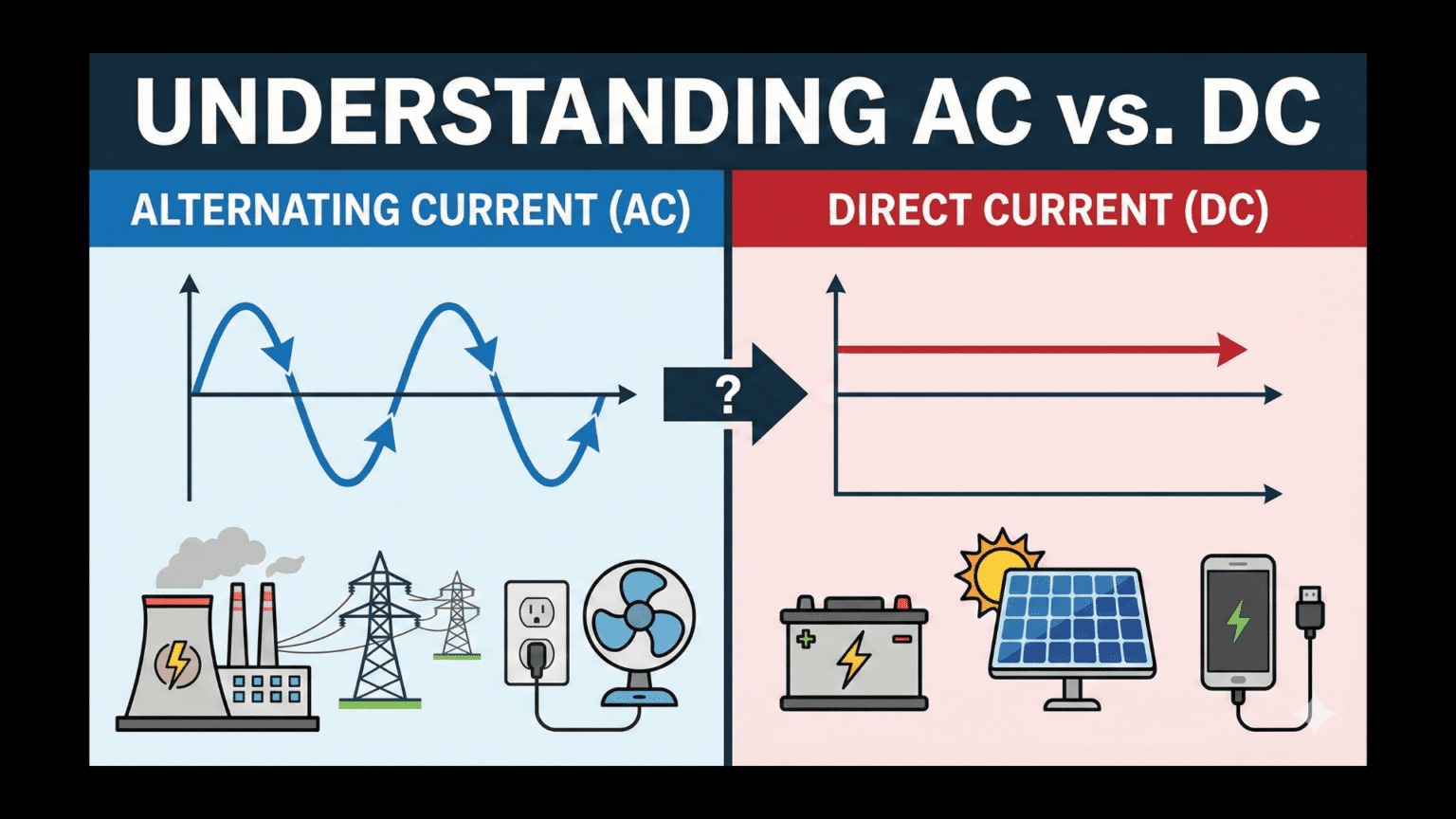
Every electrical device you use operates on one of two fundamentally different types of electrical current: direct current (DC) or alternating current (AC). Your smartphone battery provides DC. The wall outlet in your home supplies AC. A solar panel generates DC. The power grid delivers AC. This distinction between AC and DC represents one of the most important concepts in understanding how electrical systems work, yet many people use electricity daily without understanding what makes these two types of current different or why both exist.
The difference is not merely academic. Understanding AC versus DC helps explain why you need different chargers for different devices, why some equipment feels warm during operation, why power transmission lines work the way they do, and even why a shocking historical battle between Thomas Edison and Nikola Tesla shaped the electrical infrastructure we use today. This knowledge forms an essential foundation for anyone working with electronics or seeking to understand modern electrical technology.
This comprehensive guide will explore what makes AC and DC fundamentally different, how each type of current behaves in circuits, where each comes from, why we use both instead of standardizing on one, and how we convert between them. Rather than presenting dry technical facts, we will build genuine understanding of these two electrical current types and develop intuition for when and why each is appropriate for different applications.
Direct Current: The Steady Flow
Direct current represents the more intuitive of our two current types because it behaves consistently and predictably. Understanding DC thoroughly provides a foundation for comprehending AC’s more complex behavior.
Defining Direct Current
Direct current flows continuously in one direction through a circuit. Electrons move from the negative terminal of the power source, through the circuit components, to the positive terminal in a steady, unchanging direction. This unidirectional flow continues as long as the circuit remains closed and the power source maintains its voltage.
The term “direct” refers to this constant direction of flow. Unlike alternating current where direction reverses periodically, DC maintains the same polarity at all times. If you connect a voltmeter to a DC source, the positive probe always reads positive voltage relative to the negative probe. The voltage magnitude might vary over time as batteries discharge or loads change, but the polarity remains constant.
When we describe DC, we typically refer to pure DC where both the direction and magnitude of current remain constant. However, the term also encompasses varying DC, where current magnitude changes but direction does not reverse. A battery discharging produces decreasing DC voltage, but it remains DC because current continues flowing in the same direction despite the declining magnitude.
Sources of Direct Current
Several different mechanisms generate direct current, each with distinct characteristics that make them suitable for different applications.
Batteries represent the most familiar DC source. Chemical reactions within the battery create a charge separation that maintains voltage between the terminals. As long as reactants remain available, the battery sustains this voltage, providing steady DC output. Primary batteries like alkaline cells exhaust their reactants irreversibly. Secondary batteries like lithium-ion cells use reversible reactions, allowing recharging by forcing current through them in the reverse direction to restore the original chemical state.
Solar panels convert light energy directly into DC electricity through the photovoltaic effect. When photons strike semiconductor materials in the solar cell, they liberate electrons, creating free charge carriers that can be directed to flow as current. The output voltage depends on the semiconductor materials and cell construction, while current output depends on light intensity and cell area. Solar panel output is inherently DC, always maintaining the same polarity though voltage and current vary with sunlight conditions.
DC generators, while less common than AC generators, produce DC through mechanical energy conversion. These devices use commutators, rotating switch assemblies that reverse connections at precise moments, converting the naturally alternating output of a rotating coil in a magnetic field into pulsating DC. Though less efficient than AC generators, DC generators find use in applications requiring high-current DC without electronic conversion.
Rectifiers convert AC to DC using diodes or other switching elements. Most modern DC power supplies use rectification because AC power from the electrical grid is widely available. The rectification process creates pulsating DC that requires filtering to produce steady DC suitable for electronic devices. We will explore this conversion process in detail later.
Characteristics of DC in Circuits
Direct current exhibits several important characteristics that influence how we design and analyze DC circuits. First, DC reaches steady-state conditions where all voltages and currents become constant after any initial transient period. This steady-state behavior simplifies analysis because we need not consider time-varying effects in pure resistive DC circuits.
Second, DC does not efficiently couple through transformers. Transformers rely on changing magnetic fields to transfer energy from primary to secondary windings. DC creates a constant magnetic field that does not induce voltage in the secondary winding. This limitation prevents using transformers to step DC voltage up or down directly, requiring alternative approaches for voltage conversion.
Third, DC energy storage in magnetic fields (inductors) and electric fields (capacitors) reaches equilibrium where stored energy becomes constant. Once steady state is reached, inductors act like short circuits and capacitors act like open circuits in DC circuits. This behavior differs dramatically from AC circuits where these reactive components continuously exchange energy with the circuit.
Fourth, DC distribution over long distances faces challenges from resistive losses. Since we cannot easily transform DC to higher voltages for efficient transmission, the same power must flow at higher current when using lower voltage. Higher current through resistance creates greater power loss (P = I²R), making long-distance DC transmission historically difficult, though modern high-voltage DC systems overcome this limitation.
Applications Requiring DC
Many applications specifically require direct current due to the nature of the devices or processes involved. Electronic circuits almost universally require DC because semiconductor devices like transistors, integrated circuits, and microprocessors need stable, unidirectional current to function correctly. The consistent voltage levels enable reliable digital logic and precise analog signal processing.
Battery-powered devices necessarily use DC since batteries inherently provide DC output. This includes everything from smartphones and laptops to electric vehicles and cordless power tools. While these devices may plug into AC outlets for charging, they convert that AC to DC for battery charging and device operation.
Electrochemical processes require DC. Electroplating deposits metal onto surfaces using DC current flow through electrolyte solutions. Battery charging forces current in the reverse direction through cells, requiring DC at controlled voltage and current levels. Electrolysis breaks down compounds using DC current, finding applications from water splitting for hydrogen production to aluminum refining.
Many motors operate more efficiently or with better control characteristics on DC. Brushed DC motors provide simple speed control through voltage variation. Brushless DC motors achieve high efficiency and long life by eliminating the brushes that wear in traditional DC motors. Variable-frequency drives have made AC motors highly controllable, but DC motors remain popular for applications requiring precise speed control and high starting torque.
Alternating Current: The Oscillating Flow
Alternating current represents a more complex phenomenon than DC, but this complexity enables capabilities that make AC indispensable for power generation and distribution.
Defining Alternating Current
Alternating current periodically reverses direction, flowing first in one direction, then in the opposite direction, cycling back and forth continuously. The voltage polarity reverses in synchronization with current direction, so the terminal that is positive at one moment becomes negative half a cycle later.
This reversal follows a regular pattern, typically a sine wave shape for power distribution systems. The current smoothly transitions from maximum flow in one direction, through zero, to maximum flow in the opposite direction, then back through zero to complete one cycle. This sinusoidal variation creates the characteristic AC waveform that appears on oscilloscopes when measuring AC voltage or current.
Frequency measures how rapidly these reversals occur. In North America, AC power operates at 60 hertz (Hz), meaning 60 complete cycles per second. In most other countries, 50 Hz is standard. At 60 Hz, current reverses direction 120 times per second—60 times from positive to negative, and 60 times from negative to positive. Despite this rapid reversal, connected devices receive continuous power because the energy transfer averages out over each cycle.
The Sine Wave Character
The sinusoidal shape of AC power is not arbitrary but emerges naturally from rotating generators. As a coil rotates through a magnetic field, the voltage induced in that coil follows a sine wave pattern because the rate of magnetic field change experienced by the coil varies sinusoidally with rotation angle. This natural generation method explains why AC power universally uses sine waves.
Understanding the sine wave reveals important AC concepts. The waveform has a peak value, the maximum voltage or current reached during each cycle. It has a peak-to-peak value, measuring from maximum positive to maximum negative. It has an RMS (root-mean-square) value, which represents the equivalent DC voltage that would deliver the same power to a resistive load. When we say household voltage is 120 VAC in North America, we mean 120 volts RMS, though the peak voltage reaches approximately 170 volts.
The RMS value exists because AC voltage and current are constantly changing, making the instantaneous values less useful for power calculations than an equivalent average. The RMS value, calculated as the peak value divided by the square root of 2 (approximately 0.707), provides this meaningful average for power calculations. This is why a 120 VAC supply and a 120 VDC supply deliver similar power levels to resistive loads despite the AC voltage varying continuously between positive and negative peaks.
Sources of Alternating Current
Electromagnetic generators represent the primary source of AC power worldwide. These generators convert mechanical energy from turbines into electrical energy through electromagnetic induction. As generator rotors spin within stator magnetic fields, conductor coils cut through magnetic field lines, inducing AC voltage that naturally follows a sinusoidal pattern.
Power plant generators are driven by various energy sources. Steam turbines powered by coal, natural gas, or nuclear reactions spin generators in thermal power plants. Falling water drives turbines in hydroelectric installations. Wind spins turbine blades connected to generators in wind farms. Despite different energy sources, all these generators produce AC through the same fundamental principle of electromagnetic induction in rotating machines.
Inverters convert DC to AC using electronic switching circuits. Modern inverters use power transistors or IGBTs (insulated gate bipolar transistors) to rapidly switch DC on and off, creating a pulsating output that filters or synthesizes into AC waveforms. Pure sine wave inverters create output nearly indistinguishable from utility AC. Modified sine wave inverters create stepped approximations that work adequately for many loads while using simpler circuitry.
Oscillators generate AC signals for communication, audio, and test equipment applications. These circuits use amplifiers with positive feedback, LC resonant circuits, or crystal oscillators to create AC at frequencies ranging from a few hertz to gigahertz. While these AC signals typically operate at lower power levels than utility AC, they follow the same principle of alternating polarity and direction.
Characteristics of AC in Circuits
Alternating current exhibits behaviors that distinguish it fundamentally from DC. First, AC couples efficiently through transformers. The continuously changing magnetic field in the transformer’s primary winding induces voltage in the secondary winding, enabling easy voltage step-up or step-down without electronic conversion. This capability makes AC ideal for power distribution systems that require different voltages at generation, transmission, and consumption points.
Second, AC creates reactive effects in inductors and capacitors that store and release energy cyclically. Inductors oppose changes in current, causing current to lag voltage. Capacitors oppose changes in voltage, causing current to lead voltage. These phase relationships between voltage and current introduce impedance, a frequency-dependent opposition to AC flow that combines resistance with reactance.
Third, AC enables resonance in LC circuits where inductors and capacitors exchange energy at characteristic frequencies. This resonance underlies radio tuning, filter design, and many signal processing applications. DC circuits cannot achieve resonance because the constant voltage and current prevent the energy exchange that creates resonant behavior.
Fourth, AC causes skin effect at high frequencies where current concentrates near conductor surfaces rather than distributing uniformly across the cross-section. This reduces effective conductor cross-sectional area, increasing resistance at high frequencies. Skin effect negligibly affects 50/60 Hz power distribution but significantly impacts high-frequency signal transmission and radio frequency circuits.
Applications Requiring AC
Many applications specifically need alternating current to function correctly or efficiently. AC motors, particularly induction motors, operate on AC power and dominate industrial applications due to their rugged construction, reliability, and efficiency. These motors use rotating magnetic fields created by multi-phase AC to induce current in rotor conductors, creating torque without physical electrical connections to the rotor. This eliminates brushes, reducing maintenance and extending operating life.
Power distribution systems universally use AC because transformers efficiently change voltage levels. Generating stations step voltage up to hundreds of thousands of volts for long-distance transmission, minimizing current and resistive losses. Distribution substations step voltage down for regional distribution. Service transformers reduce voltage again to household levels. This multi-stage transformation would be impractical without AC’s transformer compatibility.
Heating applications often use AC because the power delivery is effective regardless of current direction. Resistive heaters, welding equipment, and induction heating systems work equally well whether current flows in one direction or the other, making AC perfectly suitable. The heat generated depends on RMS current and resistance, both of which remain constant despite direction reversals.
Audio systems process AC signals because sound consists of pressure variations that translate to voltage variations in microphones and current variations in speakers. The AC audio signal contains frequency components from 20 Hz to 20 kHz, representing the range of human hearing. Processing these AC signals through amplifiers and filters creates the audio reproduction we hear from speakers and headphones.
The AC versus DC Debate: Historical Context
Understanding why both AC and DC exist requires examining the historical “War of the Currents” that shaped modern electrical infrastructure and revealed the practical strengths and weaknesses of each current type.
Edison’s DC System
In the 1880s, Thomas Edison championed direct current for electrical distribution. His DC system had genuine advantages for the technology of that era. DC motors were well-developed and provided excellent speed control. DC generators were reliable and well-understood. Edison’s DC lighting systems were successful commercial ventures.
However, DC distribution faced a critical limitation: voltage could not be easily transformed. Power transmission required the same voltage at generation and consumption, typically 110 volts. Low voltage transmission meant high current for any given power level, creating substantial resistive losses in distribution wires. These losses limited DC distribution to about one mile from the generating station before voltage drop became unacceptable.
This distance limitation required many small generating stations throughout cities, each serving a limited area. While technically feasible, this approach was economically inefficient and limited electricity’s reach to urban areas where sufficient customer density justified generation stations.
Tesla and Westinghouse’s AC System
Nikola Tesla developed practical AC motors and generators, and George Westinghouse commercialized this technology. The AC system’s transformative capability solved DC’s distribution problem. AC could be generated at moderate voltage, stepped up to thousands of volts for transmission, then stepped down for safe consumption.
High-voltage transmission dramatically reduced current requirements for delivering the same power, slashing resistive losses in distribution wires. A transmission line carrying 10 kW at 100 volts requires 100 amps and loses considerable power to resistance. The same 10 kW at 10,000 volts requires only 1 amp, reducing resistive losses by a factor of 10,000 (since losses depend on current squared). This efficiency enabled practical long-distance power transmission, making centralized generation economically viable.
The “War of the Currents” pitted Edison’s established DC infrastructure against Westinghouse’s superior AC transmission capabilities. Despite Edison’s considerable efforts to demonstrate AC’s dangers (including public electrocution of animals), the technical and economic advantages of AC transmission proved decisive. By the early 1900s, AC became the standard for power generation and distribution, a decision that persists today.
The Modern Perspective
With modern power electronics, we now recognize that the AC versus DC question is not either/or but rather which is optimal for each application. Long-distance high-voltage DC transmission (HVDC) has become economically viable for specific situations, particularly submarine cables and very long overland transmission lines. Solid-state converters now transform DC voltage efficiently, eliminating the transformer limitation that historically favored AC.
Renewable energy sources often generate DC (solar) or variable-frequency AC (wind) that requires conversion anyway, making the choice between AC and DC transmission more flexible than in Edison’s era. Data centers and many modern loads operate internally on DC, leading some to propose DC distribution systems for certain applications despite the entrenched AC infrastructure.
The historical AC victory was correct for its time and remains appropriate for general power distribution. However, modern technology has rehabilitated DC for specific applications where its advantages outweigh the established AC infrastructure’s benefits.
Converting Between AC and DC
Since generation often produces one current type while loads require the other, conversion between AC and DC is ubiquitous in modern electrical systems. Understanding these conversion processes reveals practical aspects of both current types.
Rectification: AC to DC Conversion
Converting AC to DC, called rectification, uses diodes or other switching elements that conduct current in only one direction. The simplest rectifier, a single diode, passes current during half of each AC cycle when the diode is forward-biased, blocking current during the other half when reverse-biased. This half-wave rectification produces pulsating DC that has the correct polarity but highly variable magnitude.
Full-wave rectification uses four diodes arranged in a bridge configuration that redirects current through the load in the same direction during both halves of the AC cycle. Current flows through the load during both the positive and negative AC half-cycles, producing pulsating DC at twice the input frequency. While still pulsating, full-wave rectified DC contains less variation than half-wave rectification.
Filtering smooths the pulsating DC into steady DC by adding a capacitor across the output. The capacitor charges when rectifier output voltage exceeds capacitor voltage and discharges into the load when rectifier output voltage falls below capacitor voltage. This charge and discharge action fills in the valleys between rectified pulses, creating relatively steady DC with small remaining ripple.
Voltage regulation further improves DC quality by actively controlling output voltage to remain constant despite input voltage variations or changing loads. Linear regulators use transistors operating in their active region to drop excess voltage, maintaining steady output at the cost of power dissipation in the regulator. Switching regulators use rapid on-off switching to efficiently regulate voltage with minimal losses.
The complete AC-to-DC power supply chain—transformer (if needed for voltage adjustment), rectifier, filter, and regulator—appears in countless devices from phone chargers to computer power supplies. Understanding this chain helps you recognize the building blocks present in power supply circuits.
Inversion: DC to AC Conversion
Converting DC to AC, called inversion, uses electronic switches to alternately connect the DC source’s positive and negative terminals to the output, creating an alternating voltage. Simple inverters create square waves by switching between positive and negative DC voltage at the desired frequency. This square wave AC works for some loads but contains harmonic frequencies that can cause problems in sensitive equipment or motors.
Modified sine wave inverters create stepped approximations of sine waves by using multiple voltage levels. A three-level output alternates between positive DC, zero, and negative DC in patterns that approximate sine waves more closely than simple square waves. These inverters work well for many loads while remaining simpler and cheaper than pure sine wave inverters.
Pure sine wave inverters synthesize clean sine waves using pulse width modulation (PWM). High-frequency switching creates pulses of variable width that filter into smooth sine waves nearly indistinguishable from utility AC. These premium inverters work with any AC equipment, including sensitive electronics and motors that might malfunction on square wave or modified sine wave power.
Inverters find applications wherever DC sources must power AC loads. Solar installations use inverters to convert solar panel DC output into grid-compatible AC. Uninterruptible power supplies (UPS) use inverters to convert battery DC into AC during power outages. Electric vehicles use inverters to drive AC motors from battery DC. Variable frequency drives use rectification followed by inversion to create adjustable frequency AC for motor speed control.
Conversion Efficiency Considerations
Every conversion between AC and DC involves losses that reduce efficiency. Rectification losses occur in diode voltage drops and transformer resistance. Filtering introduces losses in capacitor equivalent series resistance. Regulation wastes power in linear regulators or switching losses in switching regulators. A typical AC-to-DC power supply might achieve 80-95% efficiency depending on design quality and load conditions.
Inversion also introduces losses. Switching transistors dissipate power during transitions and while conducting. Filter components absorb energy. Control circuitry consumes power. Modern pure sine wave inverters achieve 90-95% efficiency at optimal loads, though efficiency decreases at very light loads where fixed losses dominate.
These conversion losses matter because many systems convert between AC and DC multiple times. Grid AC converts to DC in a power supply, then potentially back to AC in an inverter, with each conversion losing 5-15% of energy. Minimizing conversion stages improves overall system efficiency, one reason why DC distribution is attractive for certain applications despite requiring infrastructure changes.
Measuring AC and DC
Proper measurement techniques differ between AC and DC, and understanding these differences prevents measurement errors and instrument damage.
Measuring Direct Current
DC voltage and current measurements are straightforward with most multimeters. For voltage, connect the meter in parallel with the component being measured, observing polarity. Red probe to the more positive point, black probe to the more negative point. The meter displays a positive value if connected with correct polarity, negative if reversed.
For current, break the circuit and insert the meter in series with the current path, again observing polarity. Current flows into the red terminal and out of the black terminal for a positive reading. Most multimeters include fused current measurement ranges to protect against overcurrent conditions that would damage the meter.
DC measurements remain constant when measuring steady-state conditions, making readings easy to capture and interpret. Any variation indicates either measurement error, unstable circuit conditions, or AC ripple on the DC voltage.
Measuring Alternating Current
AC measurement introduces complexity because voltage and current continuously vary. Multimeters set to AC mode measure RMS values, providing readings that represent the equivalent DC values for power calculations. A meter reading 120 VAC indicates 120 volts RMS, though instantaneous voltage varies from approximately -170 to +170 volts throughout each cycle.
Polarity becomes meaningless for pure AC signals since polarity reverses every half-cycle. Most AC meters do not indicate polarity for AC measurements. However, if DC offset exists (AC signal riding on a DC level), some meters may show this offset while others measure only the AC component.
Frequency affects AC measurements, and meters have specified frequency ranges within which they accurately measure AC. Most handheld multimeters work correctly from 50 to 400 Hz, covering utility AC and audio frequencies. Higher frequencies may produce inaccurate readings as the meter’s input circuitry cannot respond quickly enough to track rapid variations.
Oscilloscopes provide more complete AC visualization, displaying actual waveforms rather than just RMS values. This reveals waveform shape, frequency, distortion, and time-varying characteristics invisible to multimeters. For troubleshooting AC circuits or analyzing signal quality, oscilloscopes provide essential information unavailable from simple multimeter measurements.
Safety Considerations in Measurement
AC and DC present different safety challenges. AC at a given RMS voltage can be more dangerous than DC at the same voltage because AC more effectively couples to the body’s nervous system. The 50/60 Hz frequency of utility AC happens to fall in a particularly dangerous range for cardiac disruption.
DC can maintain muscular contraction continuously if you grasp conductors, making it impossible to let go. AC’s alternating nature may allow release during zero-crossing moments when voltage temporarily falls to zero, though this depends on frequency and voltage level.
Both AC and DC at sufficient voltage can cause lethal shock. Voltages above 50 volts should always be considered potentially lethal regardless of current type. Proper measurement technique includes ensuring meter leads are in good condition, using meters rated for the voltages being measured, keeping one hand in your pocket when probing high-voltage circuits to prevent current paths through your chest, and never working alone on high-voltage systems.
Power Calculations: AC versus DC
Calculating power differs between AC and DC circuits, particularly when reactive components are present.
DC Power Calculation
DC power calculation is straightforward: power equals voltage times current (P = V × I). Since DC voltage and current are constant in steady-state conditions, this simple multiplication gives instantaneous power, average power, and continuous power—all are identical.
For resistive loads, we can also use P = V²/R or P = I²R, alternative forms derived from Ohm’s Law. These equations work identically for DC circuits because all quantities remain constant.
AC Power in Resistive Loads
For purely resistive AC loads, power calculation uses RMS values in the same equations as DC: P = V_RMS × I_RMS. This works because the RMS values are specifically defined to make these calculations correct for resistive loads. A 100-watt light bulb connected to 120 VAC draws approximately 0.833 amps RMS, and 120 V × 0.833 A = 100 watts.
Instantaneous power in resistive AC circuits varies throughout each cycle, reaching maximum when voltage and current simultaneously peak, and minimum (zero) when both cross through zero. However, the average power over complete cycles equals the RMS voltage times RMS current, making calculations straightforward.
AC Power with Reactive Loads
When AC circuits include inductors or capacitors, voltage and current develop phase differences. Current might lag voltage by up to 90 degrees in inductive circuits or lead voltage by up to 90 degrees in capacitive circuits. This phase difference means voltage and current do not peak simultaneously, affecting power transfer.
Real power, measured in watts, represents actual energy consumption or conversion. Reactive power, measured in VARs (volt-amperes reactive), represents energy that oscillates between source and reactive components without being consumed. Apparent power, measured in VA (volt-amperes), equals the product of RMS voltage and current, combining real and reactive power.
The power factor, the ratio of real power to apparent power, quantifies how effectively the circuit converts apparent power to useful work. Unity power factor (1.0) means all apparent power becomes real power, occurring in purely resistive circuits. Lower power factors indicate reactive components that cause voltage and current phase differences, reducing effective power utilization.
Industrial facilities often must correct poor power factors to avoid utility penalties and improve efficiency. Power factor correction typically adds capacitors to compensate for inductive loads like motors, bringing voltage and current back into phase.
Practical Implications: Choosing AC or DC
Understanding when to use AC versus DC involves considering multiple factors including availability, efficiency, control requirements, and safety.
When DC is Preferable
Battery-powered portable devices require DC since batteries provide DC output. Attempting to create AC from batteries just to convert back to DC for electronics would be wasteful and absurd. Solar installations generate DC that can either feed directly to DC loads or invert to AC for grid connection.
Electronic circuits need DC for proper operation. Semiconductors require stable voltage references and unidirectional current flow. Analog circuits need steady voltage levels for biasing. Digital circuits require defined logic levels that DC provides. While these devices might connect to AC power sources, internal power supplies convert that AC to DC for actual circuit operation.
Electrochemical processes demand DC. Plating, battery charging, electrolysis, and corrosion protection systems all require unidirectional current flow to drive desired chemical reactions. AC would drive reactions in both directions alternately, accomplishing nothing.
High-voltage long-distance transmission increasingly uses DC for specific routes. HVDC transmission eliminates reactive power issues, allows interconnection of asynchronous AC systems operating at different frequencies, and provides controllable power flow. Submarine cables almost always use HVDC because AC cables would lose too much power to cable capacitance.
When AC is Preferable
Power distribution systems use AC because transformers efficiently change voltage levels, enabling the high-voltage transmission that minimizes resistive losses. The established AC infrastructure makes AC power universally available in developed areas, creating a strong default preference.
AC motors, particularly three-phase induction motors, provide industrial workhorse devices that are rugged, reliable, and efficient. While DC motors have advantages for certain applications, AC motors dominate industrial applications due to their simple construction and elimination of brushes that wear and require maintenance.
Heating applications work equally well with AC or DC, but AC is typically used because it is readily available. Resistive heaters, welding equipment, and induction heating systems function correctly on AC power without requiring conversion.
Audio and communication signals inherently consist of AC waveforms carrying information in amplitude, frequency, and phase variations. Processing these signals requires AC-compatible components and understanding of AC circuit behavior.
Hybrid Approaches
Many modern systems use both AC and DC in complementary roles. A data center might receive AC power from the utility, convert to DC for distribution within the building, then convert to various DC voltages for servers and network equipment. This hybrid approach combines AC’s distribution advantages with DC’s efficiency for modern electronic loads.
Renewable energy systems often generate DC (solar) and AC (wind), combine them on a DC bus through rectification, then invert to AC for grid connection or convert to various DC voltages for loads. The optimal combination depends on specific generation sources, load requirements, and grid connection capabilities.
Electric vehicles receive AC from charging stations, convert to DC for battery charging, then invert DC back to AC for driving AC motors. This multi-stage conversion is economically justified because it leverages existing AC infrastructure while enabling efficient motor control and regenerative braking.
Future Trends: The DC Renaissance
While AC won the war of the currents over a century ago, modern technology is creating a DC renaissance for specific applications where DC’s advantages now outweigh AC’s established infrastructure benefits.
DC Microgrids
Microgrids that integrate solar panels, battery storage, and DC loads increasingly use DC distribution internally. Since solar panels generate DC, batteries store DC, and LED lighting and electronics operate on DC, maintaining DC throughout the system eliminates multiple conversion stages. This improves efficiency and simplifies system design.
DC microgrids work particularly well for isolated installations, disaster recovery systems, and facilities with high DC loads. While they must still interface with AC grids for backup power or excess energy export, the internal DC distribution improves efficiency when most loads are DC-native.
High-Voltage DC Transmission
HVDC transmission has expanded as power electronics become more economical and capable. Point-to-point transmission over very long distances, submarine cable installations, and interconnections between asynchronous AC grids increasingly use HVDC. China has built ultra-high-voltage DC lines transmitting over 1,000 kilometers at voltages exceeding 1,000,000 volts.
These HVDC systems use sophisticated converter stations to interface with AC grids at each end, but the DC transmission section achieves lower losses, requires fewer conductors, and avoids reactive power issues that affect AC transmission.
DC for Data Centers and Telecom
Data centers and telecommunications facilities experiment with DC distribution because their loads are predominantly DC. Servers, network equipment, and LED lighting all require DC internally. Distributing 380 VDC or 400 VDC directly eliminates individual AC-to-DC power supplies in each piece of equipment, potentially improving efficiency by several percentage points.
The efficiency gains must justify replacing the established AC distribution infrastructure and developing new standards for DC equipment and safety. For new construction or major renovations, these DC systems are increasingly economically attractive.
Continued AC Dominance for General Distribution
Despite DC’s advantages for specific applications, AC will continue dominating general power distribution indefinitely. The established AC infrastructure represents enormous investment. Transformers remain the most efficient method for voltage conversion. AC generation from renewable sources like hydroelectric and wind integrates naturally with existing grids.
The future likely holds expanding DC use in specific niches—HVDC transmission, DC microgrids, specialized facilities—while AC maintains its role in general power distribution. Understanding both current types positions you to work effectively with both established AC systems and emerging DC applications.
Conclusion: Complementary Current Types
Alternating current and direct current represent fundamentally different electrical phenomena, each with distinct characteristics, advantages, and ideal applications. DC flows steadily in one direction, providing stable voltage levels perfect for electronics, electrochemistry, and battery-powered devices. AC alternates direction periodically, enabling efficient voltage transformation through transformers and practical long-distance power transmission.
The historical “War of the Currents” established AC as the standard for power generation and distribution, a choice that remains appropriate for general-purpose electrical infrastructure. However, modern power electronics and changing load profiles have created situations where DC offers superior efficiency and simplicity, leading to expanding DC applications in transmission, distribution, and consumption.
Understanding both current types, their generation, characteristics, conversion, measurement, and applications provides essential knowledge for working with electrical systems. Whether you design circuits, troubleshoot electrical problems, install renewable energy systems, or simply seek to comprehend the technology powering modern civilization, understanding AC and DC forms a crucial foundation.
Every electrical device you use operates on one of these two current types, chosen to match the device’s requirements and available power sources. The charger converting your wall outlet’s AC to charge your phone’s DC battery demonstrates how both current types work together in complementary roles. The power grid delivering AC to your home from distant generators exemplifies AC’s transmission efficiency. The battery in your electric vehicle storing DC for later conversion back to AC for motor drive shows the sophisticated interplay between both current types in modern systems.
As you continue learning electronics, you will encounter both AC and DC circuits with increasing complexity and sophistication. The fundamental understanding you have gained here—what makes them different, where each comes from, how to convert between them, and when each is appropriate—will serve you throughout this journey, whether you pursue electronics professionally, enjoy it recreationally, or simply want to understand the electrical technology that increasingly shapes our world.