Introduction
Among the three fundamental passive components in electronics—resistors, capacitors, and inductors—the inductor often receives the least attention in beginner education. While resistors and capacitors appear in virtually every circuit and are thoroughly covered in introductory materials, inductors sometimes seem mysterious or specialized, appearing primarily in power supplies, RF circuits, and other seemingly advanced applications. Yet inductors perform essential functions that cannot be replicated by other components, making them indispensable in modern electronics despite their sometimes limited visibility.
An inductor is fundamentally a coil of wire that stores energy in a magnetic field when current flows through it. This simple description masks sophisticated behavior that enables inductors to oppose changes in current, filter signals based on frequency, store energy for later release, create resonant circuits with capacitors, and perform countless other essential functions. Unlike resistors that dissipate energy as heat or capacitors that store energy in electric fields, inductors store energy in magnetic fields, giving them unique characteristics that complement the other passive components.
Understanding inductors and their applications provides knowledge essential for working with power electronics, radio frequency circuits, signal processing, and many other domains. When you comprehend why a circuit includes an inductor, what value it should have, and what happens if it fails, you demonstrate circuit mastery that goes beyond superficial component identification. This comprehensive guide will build your understanding of inductors from fundamental principles through practical applications, developing intuition that serves you throughout your electronics journey.
The Fundamental Principle: Electromagnetic Induction
All inductor behavior ultimately derives from electromagnetic induction, the phenomenon discovered by Michael Faraday in 1831 that links changing magnetic fields to induced voltages.
Magnetic Fields from Current
When electric current flows through a conductor, it creates a magnetic field surrounding that conductor. The magnetic field strength increases with current magnitude and concentrates around the conductor, with field lines forming concentric circles around the current path. This fundamental relationship between current and magnetism underlies all inductor operation.
A straight wire produces a relatively weak, dispersed magnetic field. Coiling the wire concentrates the magnetic field, with field lines from each turn reinforcing those from adjacent turns. A tightly wound coil creates a much stronger magnetic field than a straight wire carrying the same current. Adding a ferromagnetic core (iron, ferrite, or other magnetic material) concentrates the field further, multiplying the magnetic field strength by the core material’s permeability.
This ability to create and concentrate magnetic fields transforms a simple coil of wire into a useful circuit component. The magnetic field stores energy that can be recovered when current decreases, creating the fundamental energy storage characteristic that defines inductor behavior.
Self-Inductance and Voltage Generation
When current through a coil changes, the changing magnetic field induces voltage in the coil itself—a phenomenon called self-inductance. This induced voltage opposes the change in current that created it, following Lenz’s Law which states that induced effects oppose their causes. If current increases, induced voltage opposes the increase by creating voltage that resists additional current flow. If current decreases, induced voltage opposes the decrease by creating voltage that tries to maintain current flow.
The induced voltage magnitude depends on how rapidly current changes: V = -L × (dI/dt), where V is induced voltage, L is inductance in henries, and dI/dt represents the rate of current change. This equation reveals that inductance determines the relationship between current change rate and induced voltage. Higher inductance produces higher voltage for a given current change rate. Faster current changes produce higher voltages for a given inductance.
The negative sign in the equation represents Lenz’s Law—the induced voltage opposes the change creating it. This opposition to current change makes inductors fundamentally different from resistors (which respond instantly to voltage changes) and capacitors (which oppose voltage changes but allow current changes).
Energy Storage in Magnetic Fields
The energy stored in an inductor equals one-half inductance times current squared: E = ½LI². This equation parallels the capacitor energy equation (E = ½CV²) but uses current instead of voltage, reflecting inductors’ dual relationship to capacitors. While capacitors store energy in electric fields proportional to voltage squared, inductors store energy in magnetic fields proportional to current squared.
This energy storage capability enables inductors to transfer energy between circuit elements, smooth current flow in power supplies, and temporarily store energy during switching events. The energy remains available as long as current continues flowing; interrupting inductor current releases this stored energy, potentially creating large voltage spikes if no discharge path exists.
Opposing Current Changes: The Fundamental Characteristic
Just as capacitors resist instantaneous voltage changes, inductors resist instantaneous current changes. This characteristic underlies virtually all inductor applications and distinguishes inductor behavior from resistive elements.
Current Cannot Change Instantly
Since voltage across an inductor equals inductance times the rate of current change (V = L × dI/dt), changing current instantly (infinite dI/dt) would require infinite voltage. In practical terms, this means inductor current cannot change instantaneously—it can only ramp up or down at finite rates determined by applied voltage and inductance.
This resistance to current change makes inductors “remember” their current through stored magnetic energy. An inductor carrying current will attempt to maintain that current even if the voltage source is removed or changed. This persistence of current explains many inductor behaviors including voltage spikes when current is interrupted and the smooth current transitions in inductor-based power converters.
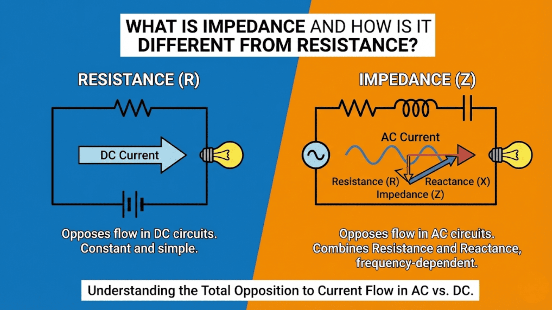
Implications for DC and AC
For DC circuits in steady state, inductors act as short circuits once current stabilizes. Since steady DC produces no current change (dI/dt = 0), no voltage is induced (V = L × 0 = 0). The inductor appears as simply its wire resistance, typically a very low value. This makes inductors nearly invisible to DC signals after transients settle.
For AC circuits, inductors present impedance that increases with frequency. The inductor’s inductive reactance X_L = 2πfL increases linearly with frequency. At low frequencies, inductive reactance is small and inductors present minimal opposition to current. At high frequencies, inductive reactance becomes large and inductors significantly oppose current flow. This frequency-dependent behavior makes inductors valuable for filtering and frequency-selective applications.
The RL Time Constant
When an inductor connects in series with a resistor (forming an RL circuit), current changes exponentially with time constant τ = L/R. After one time constant, current reaches approximately 63.2% of its final value when increasing, or falls to about 36.8% of its initial value when decreasing. This parallels RC time constants but uses different component combinations.
The RL time constant determines how quickly inductor current can change in resistive circuits. Large inductance or small resistance creates long time constants where current changes slowly. Small inductance or large resistance creates short time constants where current changes rapidly. Understanding these time constants helps predict circuit transient behavior and select appropriate component values.
Power Supply Applications: Smoothing and Conversion
Inductors play critical roles in power supplies, enabling efficient voltage conversion and current smoothing that cannot be achieved with other components.
Buck Converters: Stepping Voltage Down
A buck (step-down) switching regulator uses an inductor to efficiently convert higher input voltage to lower output voltage. The circuit alternately connects the inductor to input voltage (charging it and increasing current) and to ground through the load (discharging it and decreasing current). This switching action creates a triangular current waveform through the inductor, with average current equal to the load current.
During the on-time when the switch connects input to the inductor, voltage across the inductor equals input voltage minus output voltage, causing current to ramp up at rate (V_in – V_out)/L. During the off-time when the switch opens and a diode provides current path, voltage across the inductor reverses and current ramps down. By controlling the ratio of on-time to total cycle time (duty cycle), the converter maintains desired output voltage.
The inductor’s ability to store and release magnetic energy enables this voltage conversion with high efficiency (often 85-95%). Energy that resistive voltage dropping would waste as heat is instead stored temporarily in the inductor and delivered to the load. This efficiency advantage makes switching regulators preferable to linear regulators for most applications despite their greater complexity.
Boost Converters: Stepping Voltage Up
Boost (step-up) converters also use inductors but in a different switching arrangement that produces output voltage higher than input voltage. During the on-time, the switch grounds the inductor, allowing input voltage to drive increasing current through it, storing energy in the magnetic field. During the off-time, the switch opens and the inductor’s stored energy adds to the input voltage, delivering higher voltage to the output capacitor and load.
The inductor again provides energy storage that enables efficient voltage conversion. Without the inductor, stepping voltage up would require a transformer (which is actually a coupled inductor pair). The single-inductor boost topology provides compact, efficient voltage increase for applications from LED drivers to solar panel power optimization.
Inductor Selection for Power Supplies
Selecting appropriate inductors for switching power supplies requires considering several parameters. Inductance value determines current ripple magnitude—higher inductance produces lower ripple but requires larger, more expensive components. Saturation current must exceed peak inductor current to prevent core saturation which dramatically reduces inductance and can cause converter failure.
DC resistance (DCR) affects efficiency, with lower resistance wasting less power. Core material determines frequency capability, temperature stability, and cost. Ferrite cores suit high-frequency switching (100 kHz to several MHz) but saturate at moderate flux densities. Powdered iron cores handle higher currents but work better at lower frequencies. Selecting the right inductor involves balancing these competing requirements for the specific application.
Filtering Applications: Frequency-Dependent Impedance
Inductors’ frequency-dependent impedance makes them valuable in filter circuits that select or reject signals based on frequency.
Low-Pass Filters
An inductor in series with a load creates a low-pass filter passing low-frequency signals while attenuating high frequencies. At low frequencies where inductive reactance is small, the inductor presents minimal impedance and signals pass freely. At high frequencies where inductive reactance is large, the inductor blocks signal flow, attenuating high-frequency components.
The cutoff frequency occurs at f_c = R/(2πL), where R is the load resistance. Above cutoff, attenuation increases at 6 dB per octave (20 dB per decade). This first-order rolloff parallels RC low-pass filters but with inductor and resistor roles reversed. Using inductors instead of resistors in low-pass filters can provide advantages including the ability to handle high currents with minimal power loss.
High-Pass Filters
An inductor to ground with series resistance creates a high-pass filter blocking low frequencies while passing high frequencies. At low frequencies, the inductor’s low reactance shunts signals to ground. At high frequencies, the inductor’s high reactance presents minimal shunting, allowing signals to pass. This configuration appears in circuits requiring DC blocking with AC passage.
LC Filters
Combining inductors and capacitors creates filters with sharper rolloff than simple RC or RL filters. An LC low-pass filter uses a series inductor followed by a shunt capacitor, creating second-order filtering with 12 dB per octave rolloff. The cutoff frequency is f_c = 1/(2π√(LC)), the same equation governing LC resonance.
LC filters appear in power supply output filtering, where they reduce switching noise far more effectively than simple RC filters. The inductor carries load current with minimal loss while providing high impedance to switching frequency noise. The capacitor provides low impedance to noise while presenting high impedance to DC load current. Together, they create excellent filtering with minimal power dissipation.
Resonance and Tuning: LC Tank Circuits
Inductors combined with capacitors create resonant circuits exhibiting complex frequency-dependent behavior essential to radio communication, oscillators, and many signal processing applications.
Series and Parallel Resonance
When an inductor and capacitor connect in series, they create series resonance where impedance becomes minimum (purely resistive) at the resonant frequency f_0 = 1/(2π√(LC)). Below resonance, capacitive reactance exceeds inductive reactance and the circuit appears capacitive. Above resonance, inductive reactance exceeds capacitive reactance and the circuit appears inductive. At resonance, reactances cancel and only resistance remains.
Parallel LC circuits exhibit opposite behavior, presenting maximum impedance at resonance. This parallel resonance creates tank circuits that strongly select resonant frequency signals while rejecting others. The high impedance at resonance develops maximum voltage for signals at resonant frequency, providing the frequency selectivity essential to radio tuning and filtering.
Quality Factor and Bandwidth
The quality factor Q quantifies resonant circuit sharpness, equaling the ratio of energy stored to energy dissipated per cycle. Higher Q indicates sharper resonance with narrower bandwidth and lower losses. For an inductor, Q = 2πfL/R, where R is the total series resistance including wire resistance and core losses.
High-Q inductors are essential for selective filters and high-performance oscillators. Achieving high Q requires minimizing resistance through large wire gauge, low-loss core materials, and careful construction. The Q of practical inductors ranges from 10-50 for typical power inductors to over 100 for precision RF inductors, and even higher for specialized applications.
Applications in Radio and Communication
Radio receivers use LC tank circuits to select desired frequency signals while rejecting interference. The variable capacitor in an AM radio tunes the LC circuit’s resonant frequency across the broadcast band, selecting different stations as the capacitor varies. The high impedance at resonance develops strong signal voltage that is then detected and amplified.
Transmitters use LC circuits to generate carrier frequencies, match antenna impedance, and filter spurious emissions. The ability to create precise, stable frequencies through LC resonance is fundamental to wireless communication. Modern designs often replace variable capacitors with varactor diodes whose capacitance varies with applied voltage, enabling electronic tuning under microprocessor control.
Current Sensing and Measurement
Inductors enable current measurement through magnetic coupling without breaking the current path, a capability particularly valuable for high-current measurements.
Current Transformers
A current transformer consists of a wire carrying measured current passing through a ferromagnetic toroid with a secondary winding. Current in the primary conductor creates magnetic flux in the core, which induces voltage in the secondary winding proportional to primary current. This provides isolated current measurement without inserting resistance into the current path.
Current transformers find widespread use in AC power measurement, motor control, and protection relaying. They provide galvanic isolation between measured high-voltage circuits and measurement electronics, enhancing safety. The transformation ratio depends on the number of secondary turns—more turns increase sensitivity but decrease frequency response.
Hall Effect Current Sensors
Modern current sensors often combine inductors with Hall effect devices. The conductor carrying measured current passes through a magnetic core with an air gap. A Hall effect sensor in the gap measures magnetic field strength, which is proportional to current. This approach works for both AC and DC, unlike current transformers which only work for AC.
These sensors appear in battery management systems measuring charge and discharge currents, motor controllers implementing current limiting, and power supplies monitoring output current. The inductor core concentrates magnetic field at the Hall sensor, improving sensitivity and noise immunity compared to sensing the conductor’s field directly.
Electromagnetic Interference Control
Inductors suppress electromagnetic interference through multiple mechanisms, from filtering conducted noise to blocking common-mode interference.
Common-Mode Chokes
Common-mode chokes consist of two or more windings on a shared magnetic core, wound so that normal differential-mode signals produce opposing magnetic fields that cancel, presenting minimal inductance. Common-mode noise (signals appearing equally on all conductors relative to ground) produces fields that add, presenting high inductance that opposes this noise.
This selective impedance makes common-mode chokes valuable for blocking noise without affecting desired signals. They appear on power cords entering equipment, blocking noise conducted on power lines while not impeding power delivery. They filter communication interfaces, reducing radiated emissions without degrading signal quality.
Ferrite Beads
Ferrite beads are inductors optimized for high-frequency impedance rather than energy storage. Their lossy ferrite cores dissipate high-frequency energy as heat while presenting low impedance to low-frequency signals and DC. This makes them ideal for suppressing high-frequency noise on power lines and signal connections.
Unlike traditional inductors that store and release energy, ferrite beads absorb and dissipate it, preventing noise from reflecting back into circuits. They appear as simple cylindrical beads clamped onto cables or wires, or as surface-mount components on circuit boards. Their high impedance at noise frequencies blocks interference while minimally affecting desired signals.
EMI Filters
Complete EMI filters often combine inductors with capacitors in LC or CLC configurations. The series inductors block noise current while shunt capacitors bypass noise to ground. Multi-stage filtering provides attenuation across broad frequency ranges, meeting regulatory EMI limits while maintaining desired circuit function.
Power supply input filters, for example, typically use a common-mode choke followed by differential-mode inductors and capacitors. This combination blocks both common-mode and differential-mode noise, preventing power supply switching noise from propagating to the power grid and external noise from entering the power supply.
Motor and Relay Applications
Inductors’ magnetic properties make them essential in motors, relays, solenoids, and other electromagnetic actuators.
Motors as Inductors
Electric motors are essentially rotating inductors. Current through motor windings creates magnetic fields that interact with permanent magnets or other electromagnetic fields to produce torque. The motor windings have significant inductance that affects starting current, efficiency, and control characteristics.
Understanding motor inductance helps in proper motor control design. Pulse-width modulation motor controllers must account for motor inductance when setting switching frequency and implementing current limiting. The motor’s inductive energy storage affects braking behavior and determines whether regenerative braking can recover energy.
Relay Coils and Snubbers
Relay coils are inductors that create magnetic fields to actuate contacts when energized. The coil inductance determines pickup voltage, drop-out voltage, and response time. When relay coils de-energize, their stored magnetic energy must dissipate, potentially creating voltage spikes that damage driving transistors.
Snubber diodes across relay coils provide discharge paths for stored energy, limiting voltage spikes to one diode drop above supply voltage. This simple protection prevents transistor damage while minimizing relay de-energization time. Resistor-capacitor-diode snubbers can further control voltage and damping for demanding applications.
Solenoids and Electromagnets
Solenoids convert electrical energy to linear mechanical motion through electromagnetic force. The solenoid coil’s inductance affects pull-in force, holding force, and response time. Larger inductance increases magnetic field strength but slows response. Designers balance these competing requirements based on application needs.
Electromagnets used for lifting, holding, or clamping similarly rely on inductor principles. Their ability to generate strong magnetic fields from electrical current enables countless applications from industrial material handling to door locks to scientific instruments. The fundamental inductor principle of current creating magnetism makes these diverse applications possible.
Transformers: Coupled Inductors
While transformers are technically separate components, they consist of coupled inductors and follow the same electromagnetic principles.
Mutual Inductance
When two inductors share magnetic flux through proximity or a common core, current change in one induces voltage in the other—mutual inductance. The mutual inductance M determines induced voltage: V_secondary = M × (dI_primary/dt). This coupling enables energy transfer between electrically isolated circuits.
Transformers exploit mutual inductance through tight coupling on shared cores. Nearly all magnetic flux from the primary winding links the secondary winding, creating efficient energy transfer. The turns ratio determines voltage transformation: V_secondary/V_primary = N_secondary/N_primary.
Transformer Applications
Power transformers step AC voltages up for efficient transmission and down for safe utilization. Audio transformers match impedances and provide isolation. RF transformers couple stages while transforming impedances in communication equipment. All rely on the fundamental inductor principle of current creating magnetic flux and changing flux inducing voltage.
Understanding inductors helps understand transformers since transformers are simply coupled inductor pairs. The primary functions as an inductor storing magnetic energy; the secondary functions as an inductor recovering that energy. Core material, winding resistance, and leakage inductance affect performance in both transformers and single inductors.
Practical Considerations in Inductor Selection
Selecting inductors for real circuits requires considering parameters beyond simple inductance value.
Saturation Current
Inductor cores saturate when magnetic field strength exceeds the core material’s capability. At saturation, inductance drops dramatically and the inductor becomes essentially a resistor. This can cause catastrophic failure in switching power supplies where current increases without the expected inductive opposition.
The saturation current rating specifies maximum DC current before saturation significantly reduces inductance (typically defined as 20-30% inductance drop). For AC applications, saturation depends on peak current including both DC bias and AC amplitude. Selecting inductors with saturation current well above maximum operating current ensures reliable operation.
DC Resistance
Inductor wire has resistance that dissipates power and reduces efficiency. Lower DCR improves efficiency but requires larger wire, increasing size and cost. The DCR specification indicates how much voltage drops across the inductor at rated current and how much power it dissipates.
For power supply inductors carrying significant current, DCR directly affects efficiency. A 10 milliohm DCR inductor carrying 5 amps drops 50 millivolts and dissipates 250 milliwatts. These losses may seem small but accumulate in multi-inductor designs. Selecting low-DCR inductors improves efficiency, particularly important for battery-powered applications.
Frequency Response
Inductor performance degrades at high frequencies due to parasitic capacitance between windings and skin effect increasing wire resistance. These effects limit usable frequency range. RF inductors use specialized construction minimizing parasitics for operation into gigahertz frequencies, while power inductors optimized for lower frequencies may not function properly at high frequencies.
The self-resonant frequency (SRF) occurs where parasitic capacitance resonates with inductance, above which the component behaves capacitively rather than inductively. Always verify SRF exceeds operating frequency by adequate margin. Some datasheets specify impedance versus frequency, showing where inductive behavior transitions to capacitive behavior.
Core Material Selection
Different core materials suit different applications. Air cores have no saturation but provide low inductance per unit size. Ferrite cores provide high inductance and work well at high frequencies but saturate at moderate flux densities. Powdered iron cores handle higher currents but suit lower frequencies. Laminated steel cores work for power-frequency transformers but not high-frequency applications.
Material properties including permeability, saturation flux density, core losses, and temperature stability determine appropriate applications. Manufacturers provide extensive guidance on material selection; consulting this guidance helps optimize inductor selection for specific requirements.
Conclusion: The Magnetic Complement to Capacitors
Inductors store energy in magnetic fields just as capacitors store energy in electric fields. This complementary relationship makes inductors essential components that perform functions capacitors cannot. Where capacitors oppose voltage changes and pass AC while blocking DC, inductors oppose current changes and block AC while passing DC. Where capacitors have impedance decreasing with frequency, inductors have impedance increasing with frequency. These opposite characteristics make inductors and capacitors complementary partners throughout electronics.
Understanding inductors transforms your circuit comprehension from superficial component recognition to genuine functional understanding. When you see an inductor in a power supply, you recognize it as providing energy storage for efficient voltage conversion. When you see an inductor in a filter, you understand it’s blocking high frequencies or providing low-pass characteristics. When you see an inductor with a capacitor, you recognize the potential for resonance and frequency selectivity. This understanding enables you to design circuits confidently rather than merely copying existing designs.
Inductors may be less common than resistors and less visible than large capacitors, but they perform essential functions in switching power supplies, RF circuits, filters, motors, transformers, and countless other applications. Modern electronics would be impossible without inductors. Efficient power conversion, radio communication, electric motors, electromagnetic relays—all depend fundamentally on inductor behavior. Mastering inductors completes your understanding of the three fundamental passive components and positions you to work confidently with the full range of electronic circuits.
As you progress in electronics, develop intuition for inductor values and characteristics in different applications. Power supply inductors typically range from microhenries to hundreds of microhenries. RF inductors might be nanohenries to microhenries. Filter inductors could be anywhere from microhenries to henries depending on frequency and impedance requirements. Saturation current should exceed peak operating current by adequate margin. DCR should be minimized consistent with size and cost constraints. This developing sense of appropriate values and characteristics helps you select inductors correctly and recognize specification errors.
Inductors are the third essential passive component, complementing resistors and capacitors to provide the complete toolkit for passive circuit elements. Together, these three component types enable countless electronic functions through their unique characteristics and complementary behaviors. Understanding all three thoroughly—not just what they are, but what they do and why circuits need them—provides the foundation for mastering electronics from basic circuits to sophisticated systems.