Introduction: Your Gateway to Electronics
There’s something magical about the first time you build a circuit and watch an LED light up. It seems almost miraculous that pushing a few components into a breadboard and connecting a battery can create light. But it’s not magic; it’s electronics, and that first blinking LED represents your first step into a vast and fascinating field.
Building your first LED circuit is the traditional starting point for electronics education, and for good reason. This simple circuit teaches fundamental concepts that you’ll use in every project you ever build. You’ll learn about voltage sources, current flow, component polarity, resistance, series circuits, and the critical relationship between theory and practice. You’ll develop hands-on skills in component identification, breadboard usage, and troubleshooting. And perhaps most importantly, you’ll experience the satisfaction of creating something functional with your own hands.
This isn’t just about making an LED glow. It’s about building confidence, developing intuition about how electricity behaves, and establishing a foundation for everything that comes next. Every complex circuit, from smartphone motherboards to spacecraft computers, is ultimately built from the same fundamental principles you’ll learn by lighting this single LED.
In this comprehensive guide, we’re not just going to tell you which holes to plug components into. We’re going to walk through every step in detail, explaining why each action matters, what’s happening electrically, and how to verify that everything is working correctly. We’ll cover component selection, circuit assembly, measurement techniques, troubleshooting strategies, and variations you can explore. By the end, you won’t just have a working LED circuit; you’ll have a deep understanding of why and how it works.
Let’s begin your electronics journey by building something real.
Understanding What You’re About to Build
Before we gather components and start assembling, let’s understand exactly what we’re building and why it works. Having this conceptual foundation makes the physical construction meaningful rather than just following instructions blindly.
The Circuit’s Purpose and Function
We’re going to build the simplest possible useful electronic circuit: a battery-powered LED with a current-limiting resistor. The circuit has exactly four components connected in a loop. A battery provides voltage and energy. An LED converts electrical energy into light. A resistor limits current to protect the LED. And wires connect everything into a complete circuit so current can flow.
When you connect this circuit, electrons flow from the battery’s negative terminal, through the resistor, through the LED (causing it to emit light), and back to the battery’s positive terminal. This continuous loop of current is what makes the LED glow steadily as long as the battery has charge.
The circuit demonstrates several fundamental principles. First, it shows that circuits must form complete loops. Break the circuit anywhere and current stops, the LED goes dark. Second, it demonstrates that current is the same everywhere in a series circuit. The same number of electrons per second flows through the resistor, the LED, and back to the battery. Third, it shows how voltage divides among components in series. The battery’s voltage is split between the resistor and the LED based on their characteristics.
Why Each Component Is Necessary
Every component in this circuit serves a specific purpose, and understanding why each is necessary helps you think like an engineer rather than just following a recipe.
The battery provides the voltage that pushes electrons through the circuit. Voltage is electrical pressure, the force that makes current flow. Without a voltage source, electrons might exist in the components but they won’t move in an organized way. Think of the battery as a pump that maintains a pressure difference, with high pressure on one terminal and low pressure on the other. Electrons naturally flow from high to low pressure, just like water flows downhill.
The LED is the functional component, the reason we’re building the circuit. It converts electrical energy into light through a quantum mechanical process we’ve discussed in previous articles. The LED requires current to flow through it to generate light; no current means no light. But as we’ve learned, LEDs can’t regulate their own current, which brings us to the next critical component.
The resistor protects the LED by limiting current to a safe level. Without the resistor, the LED would draw excessive current from the battery, overheat, and destroy itself within seconds or less. The resistor acts like a restrictor valve in a water pipe, controlling flow rate. By choosing the right resistance value, we ensure enough current flows to make the LED bright, but not so much that it’s damaged.
The connecting wires complete the circuit loop, providing a low-resistance path for current. While they might seem trivial, without proper connections, the circuit simply won’t work. In our breadboard construction, the breadboard itself provides most of the connections internally, but we’ll use some jumper wires to connect the battery.
The Electrical Values We’ll Use
For this first project, we’ll use values that are safe, readily available, and produce good results. We’ll power the circuit with a 9-volt battery, which is convenient, widely available, and provides plenty of voltage to work with. We’ll use a standard red LED with a forward voltage around 2 volts. And we’ll calculate and install a resistor that limits current to approximately 10 to 15 milliamps, which provides good brightness without stressing the LED.
These specific values aren’t sacred. You could use a different voltage (anywhere from about 3 volts to 12 volts works fine with the right resistor). You could use a different color LED (though you’d need to adjust the resistor for different forward voltages). You could target a different current (anywhere from 5 to 20 milliamps works for standard LEDs). The principles remain the same regardless of the specific values you choose.
Gathering Your Components and Tools
Before you start building, you need to gather everything you’ll need. Having all components and tools ready before you begin makes the process smooth and avoids frustrating interruptions.
Essential Components
Let’s itemize exactly what you need for this project. First, you need one LED. For your first circuit, choose a standard 5-millimeter red LED. Red is the easiest color to use because it has the lowest forward voltage, giving you the most flexibility with different power sources. The LED should be a standard indicator type, not a high-power LED. If you’re buying online or at a store, anything labeled as a “5mm red LED” or “standard red LED” will work perfectly.
Second, you need one resistor. The exact value depends on your power source, but for a 9-volt battery and red LED, you want a resistor between 330 ohms and 470 ohms. These are extremely common values and should be easy to find. If you have a resistor kit, either value will be included. The resistor should be rated for at least 1/4 watt (the most common size). We’ll calculate the exact value shortly, but having these values on hand will work.
Third, you need a battery. A 9-volt battery is ideal for this first project because it provides ample voltage, includes a convenient snap connector, and is universally available. Any brand works; even a partially discharged battery should provide enough voltage for this circuit. If you don’t have a 9-volt battery, you could use four AA batteries in a holder (providing 6 volts), or even a USB power supply (5 volts), though you’d need to adjust the resistor value accordingly.
Fourth, you need a battery connector for the 9-volt battery, sometimes called a battery snap or battery clip. This is a small plastic connector with two wires (red and black) that snaps onto the battery terminals. These are inexpensive and often come with battery holders or can be purchased separately. Alternatively, if you have alligator clip leads, you can use those to connect to the battery terminals, though it’s less convenient.
Fifth, you need a breadboard, also called a solderless breadboard or prototyping board. This is a plastic board with a grid of holes that allows you to insert components and have them electrically connected without soldering. For this simple circuit, even the smallest breadboard (often called a mini breadboard with 170 tie points) is more than adequate. If you plan to continue with electronics, a medium-size breadboard with 400 or 830 tie points provides more space for future projects.
Finally, you might need a few jumper wires to make connections on the breadboard. Many breadboard kits include these. You need short wires, perhaps 3 to 5 centimeters long. If you don’t have pre-made jumper wires, you can use solid-core wire (22 or 24 gauge) cut to length with stripped ends.
Useful Tools
While you can build this circuit with just your hands, a few simple tools make the process easier and help you learn more. The most useful tool is a multimeter, a device that measures voltage, current, and resistance. Even an inexpensive multimeter (available for under ten dollars) provides valuable insight into what’s happening in your circuit. We’ll use it to verify battery voltage, check resistor values, and confirm that the LED is working before we build the circuit.
Wire strippers are helpful if you’re cutting your own jumper wires. Needle-nose pliers can help insert components into tight breadboard holes. A small LED or continuity tester is useful for checking connections, though your multimeter can serve this purpose.
You don’t need a soldering iron for this project. The entire point of using a breadboard is to build circuits without soldering, allowing easy changes and experimentation. Save soldering for future projects when you want to make permanent circuits.
Optional Components for Experimentation
Once you’ve built the basic circuit, you might want to experiment with variations. Having a few extra LEDs in different colors lets you see how forward voltage changes. Having a selection of resistor values lets you experiment with brightness. A pushbutton switch can be added to turn the LED on and off. A potentiometer (variable resistor) allows you to adjust brightness smoothly.
These optional components aren’t necessary for your first build, but they enable valuable experimentation that deepens understanding. If you’re ordering components online, consider getting small assortments rather than single pieces.
Calculating Your Resistor Value
Before we assemble the circuit, we need to calculate the correct resistor value for our specific components. This is a critical step; using the wrong resistor value can result in a dim LED, a destroyed LED, or no light at all.
Gathering the Information You Need
To calculate the resistor value, you need three pieces of information. First, you need to know your supply voltage, which is the voltage of your battery or power source. For a fresh 9-volt battery, this is approximately 9 volts, though it might be slightly higher (9.2 to 9.5 volts) when brand new. If you have a multimeter, measure the actual voltage; if not, assuming 9 volts is fine.
Second, you need to know the forward voltage of your LED. This is the voltage that appears across the LED when it’s conducting current. For a red LED, the forward voltage is typically between 1.8 and 2.2 volts. Unless you have a datasheet for your specific LED, assuming 2.0 volts is reasonable for red LEDs. Different color LEDs have different forward voltages, which is why we’re starting with red.
Third, you need to decide on the current you want flowing through the LED. This determines brightness. Standard LEDs can safely handle 20 milliamps, but good brightness is achieved with 10 to 15 milliamps, which is gentler on the LED and extends its life. Let’s target 12 milliamps for our calculation, which is a good middle ground.
Performing the Calculation
With these values established, we can calculate the required resistance using the formula we learned in the previous article. The resistance equals the supply voltage minus the LED forward voltage, all divided by the desired current. Remember to express current in amps, not milliamps, so 12 milliamps becomes 0.012 amps.
Let’s work through this step by step. The supply voltage is 9 volts. The LED forward voltage is 2 volts. Subtracting these gives us 7 volts, which is the voltage that must be dropped across the resistor. Now we divide this voltage drop by the desired current: 7 volts divided by 0.012 amps equals approximately 583 ohms.
This calculated value of 583 ohms isn’t a standard resistor value. Resistors come in preferred values, and the closest standard values to 583 ohms are 560 ohms and 620 ohms. Either of these will work well. The 560-ohm resistor will allow slightly more current (about 12.5 milliamps), making the LED marginally brighter. The 620-ohm resistor will allow slightly less current (about 11.3 milliamps), making the LED marginally dimmer and running more conservatively. For this project, either value is excellent.
If you have a resistor kit, you probably have both values and can use either one. If you only have the common values of 470 ohms or 680 ohms, those work fine too. The 470-ohm resistor will give about 14.9 milliamps (quite bright), while the 680-ohm resistor will give about 10.3 milliamps (still plenty bright). The beauty of this calculation is that it’s forgiving; you don’t need to hit the exact value to get good results.
Identifying Your Resistor
Once you’ve selected a resistor value, you need to identify the physical resistor that has that value. Most resistors use a color code system with colored bands painted around the body to indicate the resistance value.
For a 560-ohm resistor, the color bands would be green, blue, brown, and probably gold. The first two bands (green and blue) represent the digits 5 and 6. The third band (brown) represents the multiplier, which is 10. So you read this as 56 times 10, which equals 560 ohms. The fourth band (gold) indicates 5 percent tolerance, meaning the actual resistance is within 5 percent of the nominal value.
For a 470-ohm resistor, the bands would be yellow, violet, brown, and gold. That’s 4 and 7, times 10, giving 470 ohms with 5 percent tolerance.
If you’re new to resistor color codes, you might find it helpful to use an online resistor color code calculator until you memorize the common colors. Alternatively, use your multimeter’s resistance measurement function to verify the resistor value before inserting it into the circuit.
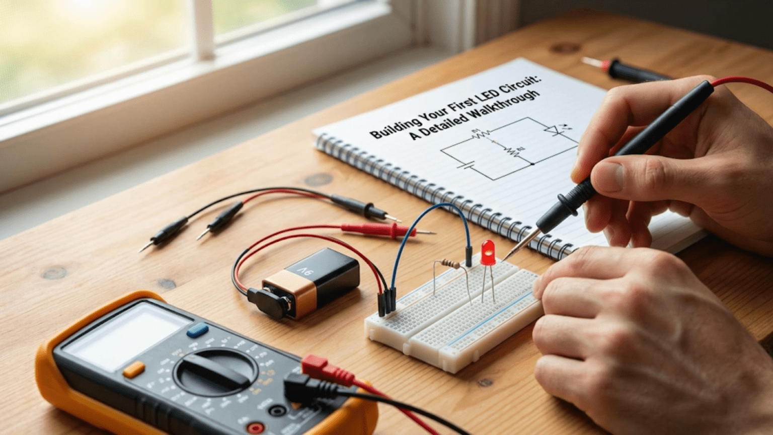
Building the Circuit on a Breadboard
Now comes the exciting part: physically building the circuit. We’ll go step by step, explaining each action and why it matters.
Understanding Your Breadboard
Before inserting components, take a moment to understand how a breadboard works. Look at your breadboard and you’ll see rows of small holes arranged in a grid pattern. These holes aren’t just mounting points; they’re electrically connected in specific patterns that allow you to build circuits without soldering.
The main area of the breadboard, typically in the middle, has rows of holes arranged in groups. In most breadboards, each row has two groups of five holes separated by a central gap. Within each group of five, all the holes are electrically connected together internally by metal strips. This means if you insert two component leads into any holes in the same group of five, they’re electrically connected. The central gap is there to accommodate integrated circuit chips, which straddle the gap.
On the edges of many breadboards, you’ll see two long rows of holes running the length of the board, often marked with red and blue lines. These are called power rails or bus strips. In these rows, all the holes are connected together along the length of the row. These are convenient for distributing power to different parts of your circuit.
For our simple LED circuit, we’ll just use the main central area of the breadboard. We’ll connect components in series, meaning we want current to flow through each component in sequence, so we’ll connect the end of one component to the beginning of the next component.
Inserting the LED
Let’s start by inserting the LED into the breadboard. Identify which lead of the LED is the anode (positive side) and which is the cathode (negative side). On a new LED, the longer lead is the anode. If the leads have been trimmed, look at the LED body; there’s usually a flat spot on one edge indicating the cathode side. When in doubt, your multimeter’s diode test function can determine polarity.
Choose a location near the middle of your breadboard. Pick any row, and insert the LED’s anode lead into one of the holes. Note which row and which set of five holes you’ve used. Now insert the LED’s cathode lead into a hole in an adjacent row. The two leads should be in different rows, not in the same row, because we don’t want them electrically connected to each other yet.
Push the leads in gently but firmly until the LED body is close to the breadboard surface, with perhaps a few millimeters of lead visible. The LED should stand upright and stable. If the leads are too long and the LED feels wobbly, you can carefully bend the leads to make the LED sit flat against the breadboard, or trim the leads slightly shorter with wire cutters.
Inserting the Resistor
Now let’s add the resistor. Resistors are not polarized, meaning they work the same regardless of which direction they’re oriented, so you don’t need to worry about which lead goes where.
We want to connect the resistor in series with the LED, meaning current flows through the resistor and then through the LED. To do this, insert one lead of the resistor into a hole in the same row where the LED’s cathode is inserted. This electrically connects the resistor to the LED’s cathode. Now insert the other lead of the resistor into a different row.
At this point, you should have the LED occupying two rows, with one lead in each row, and the resistor connecting one of those rows to a third row. Current will flow into the resistor, from the resistor into the LED’s cathode, out the LED’s anode, and from there we’ll connect to the power source.
Like the LED, push the resistor leads in firmly, and bend them if necessary to make the resistor lie flat against the breadboard. Some people like to bend the resistor leads at right angles before insertion so the resistor lays flat by default; others leave them straight and let the resistor stand up. Either approach works.
Connecting the Power Source
Now we need to connect our battery to complete the circuit. This is where the battery connector comes in. The battery connector has two wires, conventionally red for positive and black for negative, though colors can vary.
We’ll use jumper wires or stripped wire to connect the battery connector to our breadboard circuit. Take a piece of wire and insert one end into the same row as the LED’s anode. This connects the wire to the LED’s positive side. Connect the other end of this wire to the red wire from the battery connector. You can do this by twisting the wires together, or if you have alligator clips, by using those.
Take another piece of wire and insert one end into the same row as the free end of the resistor (the end not connected to the LED). Connect the other end of this wire to the black wire from the battery connector.
At this point, your circuit is complete but not yet powered. You have a series loop where current will flow from the battery’s positive terminal, through the red wire, through the LED’s anode to cathode, through the resistor, through the black wire, and back to the battery’s negative terminal. Everything is ready; you just need to connect the battery.
The Moment of Truth: Connecting the Battery
Before you snap the battery connector onto the battery, take a moment to verify your connections. Check that the LED is oriented correctly with the anode (longer lead, or the lead opposite the flat edge) connected toward the positive battery terminal. Check that the resistor is properly inserted and connecting the LED’s cathode to the negative battery terminal. Verify that all connections are secure, with wires fully inserted into breadboard holes.
When you’re confident everything is correct, snap the battery connector onto the 9-volt battery. The LED should immediately light up with a pleasant red glow. If it does, congratulations! You’ve just built your first electronic circuit. Take a moment to appreciate what you’ve accomplished. That glowing LED represents current flowing through the circuit, energy being converted from chemical energy in the battery to light energy in the LED, and most importantly, it represents your growing understanding of electronics.
If the LED doesn’t light up, don’t be discouraged. Troubleshooting is a crucial skill in electronics, and we’ll address that in detail shortly. Even experienced engineers sometimes make simple mistakes that prevent circuits from working on the first try.
What’s Happening Electrically
With the LED glowing, let’s understand exactly what’s happening electrically at this moment. The battery’s chemical reaction creates a voltage difference of approximately 9 volts between its terminals. This voltage pushes electrons through the circuit. Starting from the battery’s negative terminal, electrons flow through the black wire into the resistor.
The resistor impedes this flow, converting some electrical energy into heat. The voltage drops by approximately 7 volts across the resistor as the resistance does work against the flow of electrons. The electrons exit the resistor at a controlled rate, about 12 milliamps or 12 millicoulombs per second.
These electrons then flow into the LED’s cathode, the N-type semiconductor. They cross the PN junction where they recombine with holes from the P-type side, releasing energy as photons of red light. About 2 volts worth of energy per electron goes into this light generation process. The electrons, having given up most of their energy, exit the LED’s anode and flow through the red wire back to the battery’s positive terminal.
The circuit is in a steady state. The battery maintains 9 volts. The resistor drops 7 volts. The LED drops 2 volts. The current is 12 milliamps everywhere in the series circuit. As long as the battery has charge, this continues, with the LED converting a few milliwatts of power into visible light.
Measuring and Verifying Your Circuit
Building a circuit that works is satisfying, but measuring what’s actually happening deepens your understanding and develops crucial skills. If you have a multimeter, let’s put it to work.
Measuring Voltage Across Components
Set your multimeter to measure DC voltage, typically labeled as a V with a straight line or “DCV”. Choose a range that includes your expected voltages; many multimeters have an auto-ranging feature that selects the range automatically.
First, measure the battery voltage. Touch the red probe to the battery’s positive terminal and the black probe to the negative terminal. You should read approximately 9 volts, perhaps slightly higher if the battery is fresh. This confirms your power source is working correctly.
Now measure the voltage across the LED. Touch the red probe to the LED’s anode and the black probe to the LED’s cathode. You should read approximately 2 volts, the LED’s forward voltage drop. This measurement confirms that the LED is conducting and that your calculated value was accurate.
Next, measure the voltage across the resistor. Touch the probes to each end of the resistor. You should read approximately 7 volts, the difference between the battery voltage and the LED voltage. This confirms that the resistor is dropping the excess voltage as intended.
Here’s an important principle you’re observing: in a series circuit, the voltage drops across all components add up to the source voltage. If you measured 9 volts at the battery, approximately 2 volts across the LED, and approximately 7 volts across the resistor, then 2 plus 7 equals 9. The energy from the battery is being shared between the LED and resistor.
Measuring Current
Current measurement is slightly trickier because you need to insert the multimeter into the circuit so current flows through it. This means you need to break the circuit at some point and insert the meter in series with the other components.
Set your multimeter to measure DC current, often labeled as “A” for amperes. Make sure you’re using the correct input jacks on the meter; many multimeters have a separate jack for current measurement. Start with a higher current range (200mA or 2A range) to avoid blowing a fuse if the current is higher than expected.
Disconnect one of the wires from your circuit, creating a break in the loop. For example, disconnect the black wire from the battery connector. Now connect the multimeter in this break: one probe touching the black wire from the circuit, the other probe touching the battery connector’s black wire. Current now flows from the battery, through your circuit, through the multimeter, and back to the battery.
You should read approximately 12 milliamps (0.012 amps), confirming your calculation. This measurement demonstrates another important principle: in a series circuit, current is the same everywhere. You could measure current by breaking the circuit anywhere, before the resistor, after the resistor, before the LED, after the LED, and you’d measure the same current value.
After taking your measurement, reconnect the circuit and remove the multimeter. Always remember to reconfigure your multimeter for voltage measurement after measuring current; leaving it in current mode and accidentally trying to measure voltage can damage the meter.
Understanding What the Measurements Tell You
These measurements aren’t just numbers; they’re confirmation of Ohm’s law and Kirchhoff’s laws in action. You calculated that a certain resistor value would give a certain current, and your measurements confirm the calculation. You predicted voltage drops based on component characteristics, and the measurements match.
This is the power of electronics: you can predict circuit behavior mathematically before you build anything, then verify those predictions with measurements. As you advance in electronics, you’ll build increasingly complex circuits, but this same process of calculation, construction, and verification remains fundamental.
Troubleshooting: When Things Don’t Work
If your LED didn’t light up when you connected the battery, don’t worry. Troubleshooting is a skill worth developing, and fixing a non-working circuit teaches you as much as building a working one teaches.
Systematic Troubleshooting Approach
When a circuit doesn’t work, resist the temptation to randomly change things hoping to stumble upon a solution. Instead, work systematically, testing one possibility at a time. Start with the most likely and easiest-to-check problems before moving to more obscure possibilities.
The first thing to check is the battery. Use your multimeter to verify it has voltage. A battery that’s been sitting unused for months might be dead. A 9-volt battery should read at least 8 volts to be useful; anything less and it may not provide enough voltage for the circuit.
Second, verify LED polarity. This is the most common mistake. Try reversing the LED leads. If the LED is backwards, it won’t conduct current and won’t light. Simply pull it out of the breadboard and reinsert it the opposite way. If the LED now lights up, you’ve found and fixed the problem.
Third, check all your breadboard connections. Make sure component leads are fully inserted into holes. Make sure you’ve connected components in series properly, with each component’s end connected to the next component’s beginning. A common breadboard mistake is inserting both leads of a component into the same group of five holes, which shorts the component out.
Fourth, verify the resistor value. If you accidentally used a very large resistor value, like 100,000 ohms instead of 470 ohms, the current would be too small to light the LED visibly. Check the color bands or measure the resistor with your multimeter.
Fifth, test the LED itself. Sometimes LEDs are defective or get damaged during handling. Try connecting the LED directly to a lower voltage source like a 3-volt coin cell battery. If the LED still doesn’t light, it may be damaged. Try a different LED.
Using a Multimeter for Troubleshooting
Your multimeter is an invaluable troubleshooting tool. Measure voltage at different points in the circuit to trace where voltage is being lost. If you measure 9 volts at the battery but 0 volts at the LED, there’s a break in the connection somewhere between those points.
Use the continuity test function if your multimeter has one. This emits a beep when the probes are connected through a low-resistance path. You can check whether breadboard connections are good, whether wires are intact, and whether solder joints (in future projects) are solid.
Measure resistance in the circuit with the power off. If you measure very low resistance (near zero) across the battery connections with everything disconnected, you may have a short circuit somewhere. If you measure very high resistance (infinite or over-range), you may have a break in the circuit.
Common Mistakes and Quick Fixes
Let’s review some specific mistakes beginners often make. Installing the LED backwards is so common that you should always suspect this first if the LED doesn’t light. The fix is simple: reverse it.
Using a resistor value that’s too high is another common error. If you accidentally grabbed a 47k resistor instead of a 470-ohm resistor (the color bands look similar at a quick glance), the current would be too low for visible light. Double-check your resistor value.
Poor breadboard connections cause many failures. Breadboard holes can wear out with repeated use, or component leads might not make good contact. Try moving the circuit to a different area of the breadboard. Make sure leads are straight, not bent in ways that prevent good insertion.
Dead batteries are obvious but often overlooked. If you’re using an old battery from a drawer, test its voltage. Even batteries that show some voltage might not have enough current capacity to light an LED properly.
Experimentation and Learning More
Once you have a working LED circuit, the real learning begins through experimentation. Changing variables and observing results builds intuition that no amount of reading can provide.
Varying the Resistor Value
Try different resistor values and observe how LED brightness changes. Use a 220-ohm resistor and the LED gets noticeably brighter. Use a 1,000-ohm resistor and it gets dimmer. Use a 10,000-ohm resistor and it barely glows. This demonstrates the relationship between current and brightness.
Calculate the expected current for each resistor value and verify with measurements. This reinforces the calculations and builds confidence that you can predict circuit behavior.
Be careful not to use too small a resistor. A 100-ohm resistor with a 9-volt supply would allow about 70 milliamps through a red LED, which could damage it. Always calculate before substituting values.
Trying Different LED Colors
If you have LEDs in different colors, try replacing the red LED with green, yellow, or blue. Notice that with the same resistor, different colors have different brightness levels. This is because different colors have different forward voltages.
Measure the forward voltage across each color LED. You’ll find that blue and white LEDs drop about 3 to 3.5 volts, while red drops only about 2 volts. This explains why blue LEDs are dimmer with the same resistor; less voltage is available to push current through the resistor.
Calculate the appropriate resistor for each color LED to get the same current through each. You’ll find that blue LEDs need smaller resistor values than red LEDs. This is practical experience with the resistor calculation formula.
Adding a Switch
Enhance your circuit by adding a switch in series. A simple pushbutton switch can turn the LED on when pressed and off when released. This introduces the concept of circuit control and switching.
Connect the switch anywhere in the series loop. You could put it between the battery and the resistor, between the resistor and the LED, or between the LED and the battery; it works the same in all positions because current through a series circuit is uniform.
This teaches an important lesson: in series circuits, the order of components doesn’t affect current flow. Whether the resistor comes before or after the LED makes no electrical difference.
Multiple LEDs
Try adding more LEDs to your circuit. You can connect multiple LEDs in series, which means they share the current but the voltages add up. With a 9-volt battery, you could light three or four red LEDs in series with an appropriate resistor.
Calculate the total LED voltage by adding the forward voltages. Three red LEDs at 2 volts each total 6 volts. Subtract from 9 volts to get 3 volts for the resistor. Divide by your desired current to get the resistor value.
You can also connect multiple LED-resistor pairs in parallel, each branch with its own current-limiting resistor. This maintains proper current through each LED regardless of variations in forward voltage. This is the correct way to operate multiple LEDs from one power source.
Understanding the Broader Context
This simple LED circuit connects to much broader concepts in electronics that you’ll encounter as you continue learning.
Series Circuits as a Foundation
The series circuit you’ve built demonstrates principles that apply to all series circuits. Components in series share current but divide voltage. The same current flows through every component. The sum of voltage drops equals the source voltage. These principles work whether you have two components or two thousand.
Understanding series circuits prepares you for more complex configurations. Many practical circuits combine series and parallel sections. Being comfortable analyzing series configurations is essential for understanding these more complex circuits.
Power and Energy Concepts
Your LED circuit is converting energy from one form to another. The battery stores chemical energy. The circuit converts this to electrical energy (moving charges). The resistor converts electrical energy to heat. The LED converts electrical energy to light (and some heat).
Calculate the power dissipated by each component. Power equals voltage times current. The resistor dissipates about 7 volts times 12 milliamps, which equals 84 milliwatts. The LED dissipates about 2 volts times 12 milliamps, which equals 24 milliwatts. The total circuit power is about 108 milliwatts, which must equal the battery power output of 9 volts times 12 milliamps.
Understanding power helps you design circuits that don’t overheat, choose appropriate component ratings, and estimate battery life.
Component Ratings and Safety Margins
Every component has maximum ratings that shouldn’t be exceeded. LEDs have maximum current ratings. Resistors have maximum power ratings. Batteries have maximum current delivery capabilities.
Good engineering practice includes safety margins. If an LED is rated for maximum 20 milliamps, operating it at 12 milliamps provides a margin that extends lifetime and accounts for variations in manufacturing and operating conditions.
This principle applies to all electronics design. Understanding and respecting component limits prevents failures and creates reliable circuits.
From Breadboard to Beyond
While breadboards are perfect for learning and prototyping, eventually you might want to make more permanent versions of your circuits.
Soldering Your Circuit
Once you’re confident your circuit works correctly, you can transfer it to a permanent form by soldering components to a perfboard or printed circuit board. Soldering creates permanent electrical and mechanical connections.
The circuit remains the same; you’re just changing how components are connected. Instead of breadboard internal connections, you’re creating custom connections with solder. The LED still connects to the resistor, which connects to the battery, forming the same series loop.
Learning to solder is a valuable skill, but master breadboarding first. Breadboards allow quick changes and easy fixes. Once you have a working design on a breadboard, you can confidently make it permanent through soldering.
Powering Circuits Permanently
While a 9-volt battery is convenient for experiments, it’s not the most economical or practical for permanent installations. For a night light or indicator that runs continuously, you might use a wall adapter power supply instead.
You could also power LED circuits from USB ports, which provide 5 volts. Many modern projects use microcontroller boards like Arduino that can control LED circuits, providing not just power but programmable control.
The resistor calculation works the same regardless of power source. Just use the actual supply voltage in your calculations and select the appropriate resistor value.
Next Steps in Your Learning Journey
This first LED circuit is just the beginning. The skills and knowledge you’ve developed form the foundation for much more complex projects. You understand voltage, current, and resistance practically, not just theoretically. You know how to use a breadboard, how to measure circuit parameters, and how to troubleshoot problems.
Next, you might explore circuits with multiple components, introduce switches and sensors, learn about capacitors and inductors, or start working with integrated circuits. Each new concept builds on what you’ve learned with this simple LED circuit.
The most important thing you’ve gained is confidence. You’ve built something with your own hands, applied theory to practice, and seen your calculations confirmed by reality. This confidence will carry you forward as you tackle increasingly sophisticated projects.
Conclusion: The Power of Fundamentals
There’s a reason that lighting an LED is the traditional first project in electronics education. This simple circuit teaches so many fundamental concepts: series circuits, Ohm’s law, component polarity, current limiting, power dissipation, voltage division, and practical skills like breadboarding and measurement.
But beyond the technical knowledge, this project teaches something more important: electronics is accessible. You don’t need a laboratory full of expensive equipment or years of education to build something functional. With a few dollars worth of components and some basic understanding, you can create light from electricity, converting energy and controlling current just like the most sophisticated electronics do at a larger scale.
Every complex electronic device, from your smartphone to your car to the International Space Station, is built from the same fundamental components and principles you’ve used in this first LED circuit. Resistors limit current. Semiconductors like LEDs perform specialized functions. Circuits form complete loops allowing current to flow. Power supplies provide energy. These principles don’t change whether you’re lighting a single LED on a breadboard or designing a supercomputer.
The glowing LED on your breadboard represents more than just light. It represents your first step into the vast field of electronics, your first successful application of electrical theory to physical reality, and your first experience with the satisfaction of building something that works. That small point of red light is your gateway to understanding and creating the electronic technology that shapes modern life.
As you continue your electronics journey, you’ll build on this foundation. You’ll learn about transistors that amplify signals and act as switches. You’ll discover integrated circuits that pack thousands of components into a single package. You’ll explore digital logic that processes information. You’ll work with sensors that detect the world and actuators that affect it. Every step builds on fundamentals, and those fundamentals started with this simple LED circuit.
So keep that first LED circuit. Remember the satisfaction of seeing it light up for the first time. Let it remind you that complex achievements start with simple steps, that understanding comes through hands-on experience, and that the fundamentals never stop being fundamental, no matter how far you progress. Every expert in electronics once stood where you stand now, with a glowing LED on a breadboard and a mind full of curiosity about what comes next. Welcome to electronics. Your journey has truly begun.