Introduction
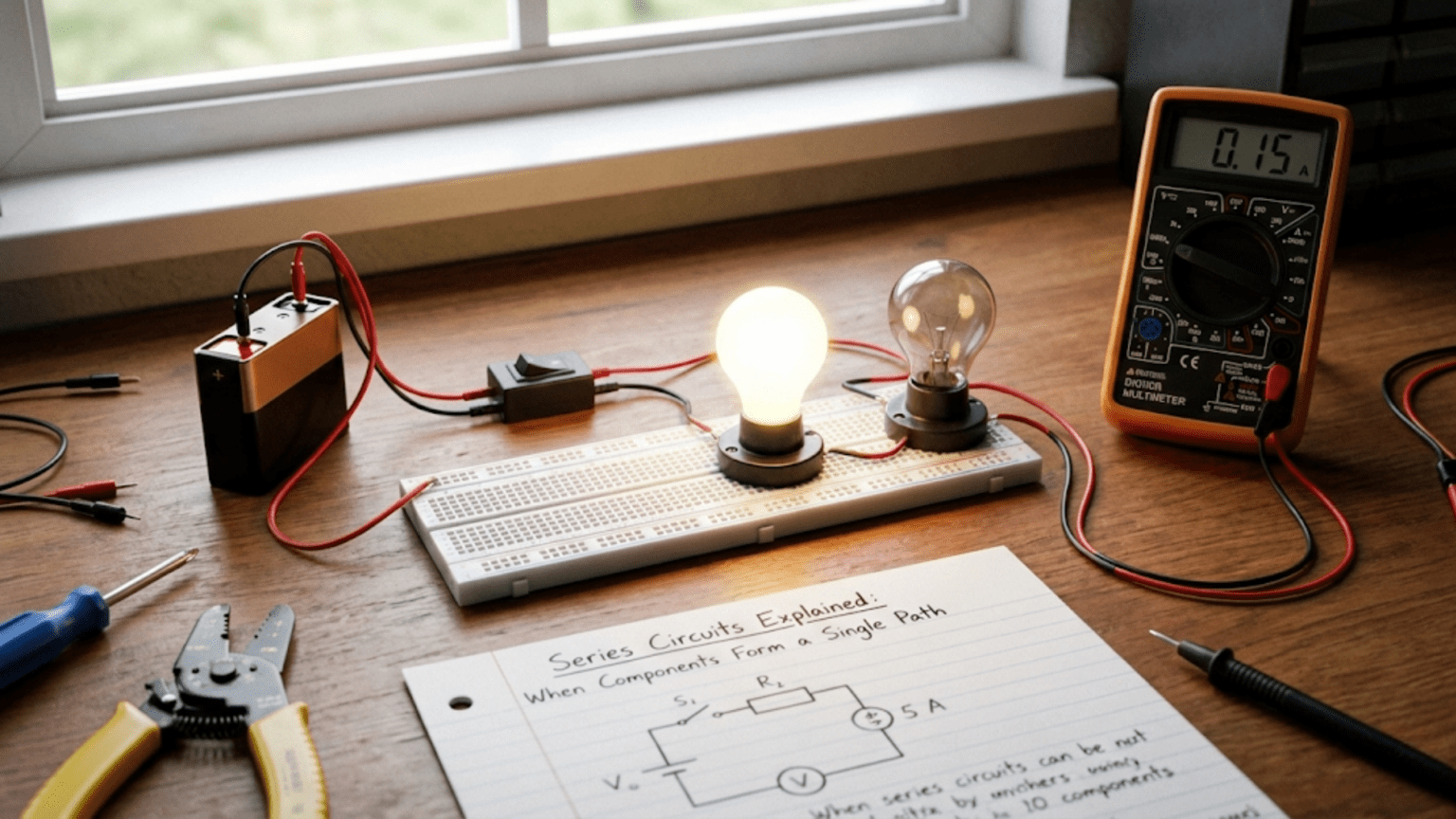
When you arrange components end-to-end in a single continuous path, you create a series circuit—one of the two fundamental circuit configurations that form the foundation of all circuit analysis. While this arrangement seems simple at first glance, series circuits exhibit specific characteristics and behaviors that you must understand thoroughly to analyze real circuits or design functional systems. Every complex circuit contains series-connected sections, making series circuit analysis an essential skill you will use constantly throughout your electronics work.
Series circuits appear everywhere in practical electronics. The simplest flashlight uses components in series: battery, switch, and bulb connected end-to-end. Voltage dividers that scale signals or set bias points use resistors in series. LED circuits typically place a current-limiting resistor in series with the LED. Filters, sensors, and countless other applications rely on series component arrangements. Understanding series circuits is not merely academic exercise but practical knowledge you will apply daily in electronics work.
The defining characteristic of series circuits—that all components carry identical current—leads to profound implications for voltage distribution, power dissipation, total resistance, and circuit behavior. These implications follow directly from fundamental circuit laws, yet beginners often find them counterintuitive initially. This comprehensive guide will build your understanding of series circuits from first principles, developing both mathematical competence in series circuit calculations and intuitive understanding that lets you predict circuit behavior without detailed calculations.
The Defining Characteristic: One Path for Current
Understanding what makes a circuit “series” requires examining the path that current follows through the circuit.
Single Current Path
In a series circuit, current has only one possible path from positive to negative terminal of the power source. Every electron flowing out of the positive terminal must pass through every component in sequence before returning to the negative terminal. There are no branch points where current can split into multiple paths; there is simply one continuous chain of components.
This single-path characteristic means you can trace the circuit with your finger from one battery terminal, through each component in order, and back to the other battery terminal without ever having to choose between multiple paths. If you encounter a junction where multiple paths diverge, the circuit is not purely series—it contains parallel elements as well.
Recognizing series connections in complex circuits requires identifying these unbranched current paths. Even in circuits with many components, you can often find sections where several components connect in series with each other, carrying the same current despite the larger circuit having parallel branches elsewhere.
The Fundamental Consequence: Identical Current
The most important consequence of series connection is that all components in the series chain carry identical current. If 100 milliamps flows through one resistor in a series string, exactly 100 milliamps flows through every other component in that string. This is not an approximation or special case—it is an absolute requirement based on conservation of charge.
Charge cannot accumulate anywhere in a conductor. If 100 milliamps enters one end of a resistor, 100 milliamps must exit the other end. The charges entering must equal charges exiting, or charge would build up inside the resistor, which does not happen in conductors. This principle, sometimes called Kirchhoff’s Current Law, ensures current remains constant throughout a series path.
This current equality makes series circuit analysis straightforward in many ways. Once you know current at any point in a series circuit, you know current everywhere in that circuit. You need not calculate current separately for each component—the same value applies throughout the series string.
Breaking the Series Chain
Any open circuit in a series chain stops current flow completely. A burned-out bulb, a broken wire, an open switch—any discontinuity breaks the series path and reduces current to zero everywhere in that series circuit. This is why old-style Christmas lights strung in series would all go dark when a single bulb burned out. The open circuit at the failed bulb broke the series chain, stopping current through all bulbs.
This vulnerability makes series circuits less reliable than parallel circuits for some applications. A single component failure disables the entire series string. However, this same characteristic provides built-in safety for some applications—a series fuse or circuit breaker protects an entire load by opening the series connection when overcurrent occurs.
Voltage Distribution in Series Circuits
While current remains constant throughout a series circuit, voltage distributes among components according to their resistance values.
Voltage Drops Across Components
Each component in a series circuit drops some portion of the total applied voltage. The voltage drop across each component equals the current (same for all series components) times that component’s resistance: V = I × R. Since current is constant but resistances differ, voltage drops differ proportionally to resistance values.
If a series circuit contains three resistors with values of 100Ω, 200Ω, and 300Ω carrying 10 milliamps, the voltage drops are 1V, 2V, and 3V respectively (V = 0.01A × R for each resistor). The resistor with twice the resistance drops twice the voltage; the one with three times the resistance drops three times the voltage. This proportional relationship makes predicting voltage distribution intuitive once you grasp the principle.
These voltage drops represent energy conversion. When current flows through resistance, electrical potential energy converts to heat at a rate equal to voltage drop times current. The component dropping more voltage at the same current dissipates more power and generates more heat. Understanding voltage drops as energy conversion helps make sense of component power ratings and heat management requirements.
Kirchhoff’s Voltage Law
The sum of voltage drops around any closed loop equals the total voltage supplied to that loop—this is Kirchhoff’s Voltage Law (KVL), one of the fundamental laws of circuit analysis. In a series circuit, the voltage drops across all components must sum to equal the applied voltage.
This law reflects energy conservation. The electrical potential energy that charges gain from the voltage source must equal the energy they lose passing through circuit resistances. Energy cannot appear from nowhere or disappear without trace; it merely converts from electrical form to heat. KVL quantifies this energy conservation in voltage terms.
For the previous example with 1V, 2V, and 3V drops, these must sum to equal the applied voltage. If a 6V battery powers this circuit, the voltage drops (1V + 2V + 3V = 6V) exactly equal the battery voltage. If you measure only 5V total across the resistors when expecting 6V, either your voltage measurement is wrong, your resistance values are different than assumed, or the battery voltage is not actually 6V.
Voltage Division: The Fundamental Series Application
Series resistors create voltage dividers, one of the most common and useful series circuit applications. By selecting resistor values appropriately, you can create any desired voltage fraction between 0V and the supply voltage.
The voltage divider equation relates output voltage to input voltage and resistor values. For two resistors in series across a voltage source, the voltage at their junction equals the input voltage times the ratio of the lower resistor to the total resistance: V_out = V_in × (R2 / (R1 + R2)). This equation lets you calculate voltage divider outputs or design dividers to produce desired voltages.
A 5V supply with equal-value resistors (say, 1kΩ each) creates 2.5V at the junction—exactly half the supply voltage. Using a 1kΩ resistor and a 4kΩ resistor creates 4V at the junction (5V × 4kΩ / 5kΩ = 4V). This precise voltage control through simple resistor selection makes voltage dividers ubiquitous in circuit design.
Series Resistance: Adding Impedances
The total resistance of series-connected resistors equals the sum of individual resistances—a straightforward relationship with important implications.
Simple Addition Rule
For resistors R1, R2, R3, etc., connected in series, total resistance R_total = R1 + R2 + R3 + … . This simple addition makes series resistance calculations trivial compared to parallel resistance calculations that require reciprocals.
The physical reason for this addition is intuitive: current must flow through each resistance in sequence, encountering cumulative opposition from each one. A 100Ω resistor followed by a 200Ω resistor presents the same total opposition as a single 300Ω resistor. The voltage drop across each portion adds up to equal the drop across the equivalent single resistor.
This additive property means series resistance always exceeds the largest individual resistance in the series string. Adding any resistor in series increases total resistance, which decreases current (for fixed applied voltage) and decreases power dissipation (since P = V² / R increases when R increases if V is constant).
Calculating Current from Total Resistance
Once you know total series resistance, calculating circuit current is straightforward using Ohm’s Law: I = V / R_total. The applied voltage divided by total series resistance gives current, which is identical through all series components.
For a 12V battery powering series resistors of 100Ω, 200Ω, and 300Ω, total resistance is 600Ω and current is 12V / 600Ω = 0.02A = 20mA. This 20mA flows through each resistor, dropping 2V, 4V, and 6V respectively (V = I × R for each resistor), and these voltage drops sum to 12V as required by KVL.
This approach—calculate total resistance, then calculate current, then calculate individual voltage drops—provides a systematic method for analyzing any series resistive circuit. The same procedure works regardless of how many series components exist.
When Series Resistance Gets Complicated
Real components have complex impedances rather than pure resistance, particularly at AC frequencies where capacitive and inductive reactance become significant. However, the series addition principle still applies: total series impedance equals the sum of individual impedances, though the arithmetic becomes more complex involving complex numbers to handle phase relationships.
For DC analysis and low-frequency AC analysis where reactive effects are negligible, treating components as pure resistances simplifies calculations without significant error. For high-frequency analysis, proper impedance calculations using complex arithmetic become necessary, but the fundamental series addition principle remains valid.
Power Dissipation in Series Circuits
Understanding how power dissipates in series circuits is essential for component selection, thermal management, and efficiency optimization.
Individual Component Power
Each component in a series circuit dissipates power according to P = I² × R, where I is the current (same for all series components) and R is that component’s resistance. Since current is constant throughout the series circuit, components with higher resistance dissipate more power.
For our previous example (20mA through 100Ω, 200Ω, and 300Ω resistors), power dissipations are:
- 100Ω resistor: P = (0.02A)² × 100Ω = 0.04W = 40mW
- 200Ω resistor: P = (0.02A)² × 200Ω = 0.08W = 80mW
- 300Ω resistor: P = (0.02A)² × 300Ω = 0.12W = 120mW
The 300Ω resistor dissipates three times the power of the 100Ω resistor despite carrying the same current, because it has three times the resistance. This matters for component selection—the 300Ω resistor needs higher power rating than the 100Ω resistor even though they are in the same series circuit.
Total Circuit Power
Total power dissipated in a series circuit equals the sum of individual component power dissipations, or equivalently, equals applied voltage times total current: P_total = V × I. For our example, total power is 12V × 0.02A = 0.24W = 240mW, which equals the sum of individual power dissipations (40mW + 80mW + 120mW = 240mW).
This total power must come from the power source. A battery supplying a series circuit delivers power at the rate P = V × I, and this power dissipates entirely in the circuit resistances (assuming ideal wires and switches with zero resistance). Understanding power flow helps predict battery life, heat generation, and efficiency.
Component Power Rating Selection
Each component must have power rating exceeding its power dissipation with adequate safety margin. A component dissipating 120mW should use at least a 1/4W (250mW) rated resistor, preferably a 1/2W (500mW) resistor for good safety margin. Using undersized components leads to overheating, possible component failure, and potential fire hazard.
The squared relationship between current and power (P = I²R) means small current increases cause large power increases. Doubling current quadruples power dissipation. This sensitivity makes power calculations essential for any circuit design or modification. Never increase current without verifying that component power ratings remain adequate.
Series Circuit Applications
Series connections appear throughout practical electronics, enabling numerous useful functions.
Current Limiting
Placing a resistor in series with a load limits current to safe values regardless of load characteristics. LED circuits use series resistors to limit current to the LED’s rated value. Transistor base circuits use series resistors to limit base current. Any circuit requiring precise current control benefits from series current-limiting resistors.
The series resistor must drop the excess voltage that the load cannot handle. For an LED with 2V forward voltage powered from 9V with 20mA desired current, the series resistor must drop 7V at 20mA: R = V / I = 7V / 0.02A = 350Ω. Standard 330Ω or 360Ω resistors provide close approximations. The resistor must handle 140mW (P = I²R = 0.0004 × 350 = 0.14W), requiring at least 1/4W rating.
Voltage Division for Bias and Reference
Series resistor dividers create intermediate voltages from available supply voltages. Transistor bias networks, comparator reference inputs, analog-to-digital converter references—countless applications require specific voltages that dividers generate from standard power supplies.
Divider design requires selecting resistor values to produce desired voltage while considering current draw, loading effects, and power dissipation. Higher resistance values consume less power but are more affected by loading. Lower resistance provides stiffer voltage source but wastes power. Typical designs use the minimum resistance consistent with acceptable power dissipation, ensuring the divider can supply reasonable load current without voltage sag.
Impedance Matching and Attenuation
Series resistors adjust impedance or attenuate signals. A series resistor before a capacitive load creates an RC low-pass filter. Series resistance between stages isolates them, preventing oscillation while minimally loading the driving stage. Audio attenuators use series resistances to reduce signal levels by precise amounts.
These applications exploit series resistance’s ability to drop voltage and limit current. By choosing appropriate values, designers control signal levels, protect sensitive inputs, and achieve desired impedance characteristics using simple, reliable series resistors.
Sensor Interface Circuits
Many sensors require series resistors for proper interfacing. A thermistor in series with a fixed resistor creates a voltage divider whose output varies with temperature. Photoresistors in series dividers create light-sensitive voltage sources. Strain gauges in bridge configurations use series/parallel resistor networks to convert mechanical strain to voltage changes.
The series arrangement with sensors provides robust, simple interfacing. The fixed resistor sets the sensitivity and output voltage range, while the variable sensor resistance creates voltage changes that electronics can measure and process.
Analyzing More Complex Series Circuits
Real series circuits often contain more than just resistors, requiring expanded analysis techniques.
Series Switches and Fuses
Switches and fuses in series control or protect circuits. An open switch stops current flow completely, making all series components inactive. A blown fuse opens the series path, protecting downstream components from overcurrent.
Multiple switches in series create AND logic: all switches must close for current flow. This provides safety interlocks where multiple conditions must be satisfied simultaneously. Emergency stop circuits often use series switches at multiple stations, ensuring any single switch can stop the system.
Series Voltage Sources
Batteries connected in series add their voltages. Three 1.5V AA batteries in series provide 4.5V. This voltage addition enables creating higher voltages from low-voltage cells. However, all batteries must carry the same current, so series connection does not increase current capacity—it only increases voltage.
Improper series battery connection can cause problems. Mixed battery types or conditions create unequal voltages that can reverse-charge weaker batteries. Always use matched batteries of the same type, age, and charge state in series connections. Replace all series batteries simultaneously rather than replacing individual cells.
Series Capacitors
Capacitors in series combine like resistors in parallel (using reciprocals): 1/C_total = 1/C1 + 1/C2 + 1/C3 + … . This means series capacitance is less than the smallest individual capacitance. Series capacitors share charge but develop different voltages inversely proportional to their capacitances.
Series capacitor connections appear when voltage rating requirements exceed individual capacitor ratings. Two 100V capacitors in series safely withstand 200V (voltage divides between them). This technique extends voltage capability while accepting reduced capacitance. Resistors across each capacitor ensure voltage divides evenly despite manufacturing tolerance variations.
Series Inductors
Inductors in series add directly like resistors: L_total = L1 + L2 + L3 + … . This increases total inductance, useful when single inductors with required inductance are unavailable or when physical constraints make one large inductor impractical compared to multiple smaller ones.
However, mutual inductance between nearby inductors can affect total inductance unpredictably. If inductors couple magnetically, their combined inductance might exceed or be less than the arithmetic sum depending on coupling polarity. For predictable results, separate series inductors physically or shield them to minimize magnetic coupling.
Common Series Circuit Mistakes
Several errors appear repeatedly in beginner’s series circuit analysis and design.
Forgetting That Current Is Constant
The most common mistake is calculating different currents for different series components. Since current is identical throughout a series path, calculating it once gives the value for all components. A related error is assuming current “gets used up” as it flows through components. Current remains constant; voltage drops as energy converts to heat, but current magnitude does not change.
This mistake often leads to incorrect power calculations. If you calculated current incorrectly for a component, your power calculation (P = I²R) will be wrong. Always verify that your calculated currents are identical throughout series paths before calculating voltages or powers.
Incorrect Voltage Drop Calculations
Some beginners calculate voltage drops without considering that all voltages must sum to the source voltage. If individual drops sum to more or less than the source voltage, calculations contain errors. Always verify KVL: sum of voltage drops around any loop equals applied voltage.
Another voltage error is applying the wrong voltage in divider calculations. The voltage divider equation uses the voltage across the entire divider, not some other voltage in the circuit. Applying incorrect voltage produces incorrect output calculations.
Mixing Series and Parallel Formulas
Resistances add for series circuits but combine using reciprocals for parallel circuits. Confusing these formulas is a common error. Remember: series resistances add directly; parallel resistances combine through reciprocals. The formulas are not interchangeable.
One memory aid: series configuration has resistors in a row (series, like serial numbers in a sequence), and values add in a row (simple addition). Parallel configuration has resistors side-by-side, and the formula is more complex (reciprocals).
Ignoring Component Tolerances
Real resistors have tolerances (typically 5% or 10% for common resistors). When calculating voltage division, actual resistances may differ from nominal values due to tolerance, causing actual voltage division ratios to differ from calculated values. For critical applications, use precision resistors (1% or 0.1% tolerance) or measure actual resistance values and calculate based on measured values.
Component tolerances accumulate in series circuits. The total resistance tolerance roughly equals the root-sum-square of individual tolerances for uncorrelated variations. Two 10% resistors in series create total resistance with approximately 14% tolerance (√(10² + 10²) = 14.1%). This tolerance accumulation affects voltage division accuracy and must be considered in precision applications.
Overloading Voltage Dividers
Voltage dividers work best when load current is much smaller than divider current. If load current approaches or exceeds divider current, the load significantly affects output voltage. The divider equation assumes infinite load impedance (zero load current); finite load impedance causes actual voltage to fall below the calculated unloaded value.
Design dividers with current capacity at least 10 times expected load current, accepting the associated power waste, or use voltage followers (op-amp buffers) to isolate dividers from loads. Never assume a divider will maintain its calculated voltage under arbitrary loading.
Series Circuit Troubleshooting
When series circuits malfunction, systematic troubleshooting identifies problems efficiently.
No Current Flow
When current does not flow in a series circuit, the series path contains an open circuit. Systematically check each component and connection. A broken wire, cold solder joint, open switch, blown fuse, or failed component creates the open circuit that stops current.
Visual inspection often reveals obvious problems: burned components, broken wires, or lifted traces. If visual inspection finds nothing, resistance measurement across each component identifies opens. Components in series should show their rated resistance; open circuits show infinite resistance. An unexpected infinite resistance reading identifies the failed component or connection.
Wrong Current or Voltage
If current flows but is wrong magnitude, total resistance differs from expected. Measure resistance across the entire series string and compare to calculated value. Incorrect resistance indicates wrong component values, incorrect assumptions about circuit configuration, or component failures that changed resistance.
Individual voltage drops verify component values. Measure voltage across each series component. Compare measured voltages to values calculated using Ohm’s Law with measured current and nominal component values. Discrepancies indicate that component is not the assumed value. Some possibilities: wrong component installed, damaged component with changed resistance, or incorrect resistance assumption.
Intermittent Operation
Intermittent problems in series circuits often result from poor connections that conduct sometimes but not reliably. Cracked solder joints, dirty switch contacts, corroded terminals, or loose connections create intermittent opens. Wiggling wires while monitoring circuit operation may reveal intermittent connections by causing failures to appear or disappear.
Temperature-related intermittent failures suggest components that fail when hot or cold solder joints that break with thermal cycling. Operating the circuit through temperature extremes may reproduce the intermittent fault consistently, enabling identification and repair.
Series Circuits in Practical Applications
Understanding how real applications use series circuits reinforces theoretical knowledge.
LED Indicator Circuits
A simple LED indicator uses three series components: power source, current-limiting resistor, and LED. When power applies, current flows through all three components in series. The resistor limits current to safe values for the LED. The LED drops its characteristic forward voltage (typically 2-3V depending on LED color and type).
Calculating the series resistor: R = (V_supply – V_LED) / I_desired. For a red LED (2V forward voltage) powered from 5V with 10mA desired current: R = (5V – 2V) / 0.01A = 300Ω. Use standard 330Ω resistor for close approximation. The resistor dissipates 30mW (P = I²R = 0.0001 × 300), well within 1/4W resistor rating.
String Lighting
Traditional incandescent Christmas lights often connect in series, with 20-50 bulbs sharing line voltage. Each bulb drops a fraction of total voltage, with voltages summing to line voltage. The advantage is that low-voltage bulbs (2.5V or 3.5V) can operate directly from 120V line voltage without transformers.
The disadvantage is that any single bulb failure opens the series path, extinguishing all bulbs. Modern series light strings use shunt resistors in each bulb socket that conduct when bulbs fail, maintaining circuit continuity so remaining bulbs stay lit. This clever solution preserves series efficiency while improving reliability.
Voltage Reference Circuits
Precision voltage references often use resistor dividers to create specific voltages from stable sources. A 2.5V reference might derive from a 5V reference divided by equal resistors. Temperature-compensated dividers use resistors with matched temperature coefficients, ensuring voltage ratio stability over temperature.
For high-precision applications, the divider uses precision resistors (0.1% tolerance or better) and operates from a buffered source or into high-impedance load to prevent loading effects from affecting accuracy. The divider resistances are high enough to minimize self-heating but low enough to avoid noise pickup and leakage current effects.
Conclusion: The Foundation of Circuit Analysis
Series circuits represent one of the two fundamental circuit configurations, exhibiting specific characteristics that distinguish them from parallel circuits. The defining characteristic—identical current through all series components—leads directly to voltage division proportional to resistance, total resistance equal to the sum of individual resistances, and power dissipation patterns determined by resistance distribution. Understanding these characteristics thoroughly enables analysis of any series circuit and recognition of series sections within complex circuits.
The practical applications of series circuits are countless: current limiting, voltage division, sensor interfacing, impedance matching, signal attenuation, and many more. Every complex circuit contains series-connected sections, making series circuit analysis essential knowledge for all circuit work. When you see components connected end-to-end in a schematic, immediately recognize them as series components sharing common current and consider the implications for voltage distribution and power dissipation.
Common mistakes in series circuit analysis—forgetting that current is constant, incorrectly calculating voltage drops, mixing series and parallel formulas, ignoring tolerances, and overloading dividers—can be avoided through systematic application of series circuit principles. Always verify that voltage drops sum to source voltage (KVL), that current is calculated once and applied to all series components, and that power calculations use correct current values.
Troubleshooting series circuits requires understanding their vulnerability to open circuits that stop current flow completely. Systematic checking of continuity, resistance values, and voltage drops identifies problems efficiently. Understanding what voltages and currents should exist in a properly functioning series circuit guides troubleshooting by revealing where measurements deviate from expected values.
Series circuits provide the foundation for understanding more complex circuits that combine series and parallel elements. Master series circuit analysis, and you have established one of the two pillars supporting all circuit analysis. Combined with parallel circuit understanding, series circuit knowledge enables you to analyze any passive circuit, design voltage dividers and current limiters, select appropriate component values, and troubleshoot problems systematically. This fundamental knowledge serves throughout your electronics journey, from first LED circuits through sophisticated analog and digital systems. The time invested understanding series circuits thoroughly pays dividends in every subsequent circuit you encounter.