Moving a robot circuit from breadboard to permanent form means choosing among several approaches—perfboard (drilling holes and hand-wiring with soldered connections), stripboard (pre-connected copper strips that are cut to create the desired circuit), terminal block wiring (screw or spring connectors for modular, tool-free assembly), or custom PCBs (professionally manufactured or home-etched boards with copper traces replacing all wiring)—with the right choice depending on circuit complexity, required reliability, quantity needed, budget, and the builder’s soldering and design skills.
Introduction
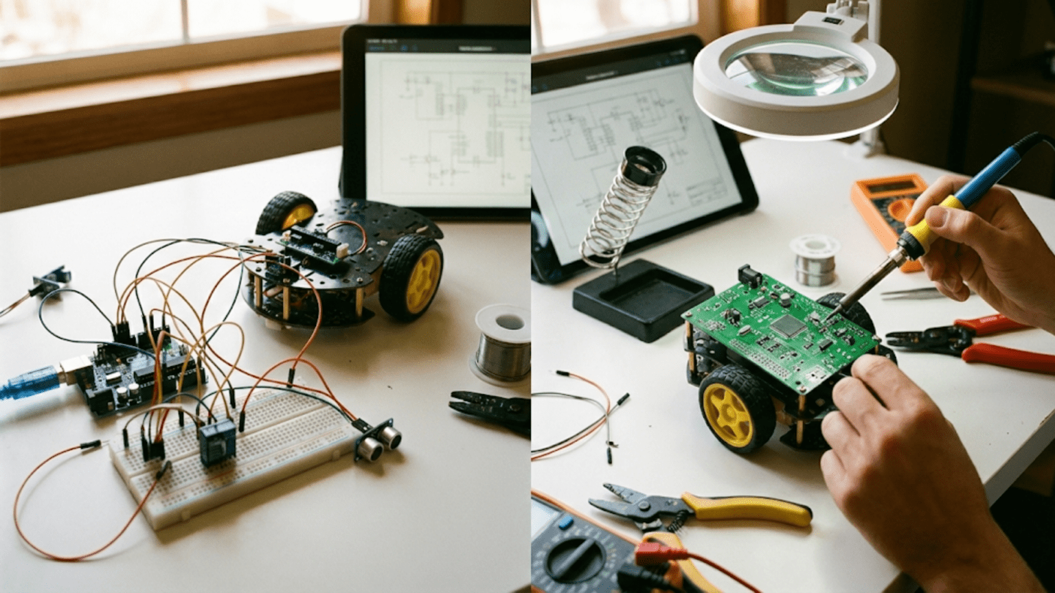
You’ve built a circuit on the breadboard. It works reliably. The sensors give accurate readings, the motors respond correctly, the microcontroller runs the right code. Now you want to install it in the robot and actually use it — and you know the breadboard won’t survive the vibration, the connector bumping, and the general mechanical stress of a real robot in operation.
This is the transition point that every robotics builder eventually reaches: the circuit has been proven, the design is stable, and it needs to become permanent. But “permanent circuit” encompasses a wide range of options, from simple point-to-point wiring with terminal blocks all the way to professionally manufactured custom PCBs. Each option has a different cost, skill requirement, time investment, and result quality.
Understanding the landscape of permanent circuit options — what each one is, how it works, when it’s appropriate, and how to execute it well — is the knowledge that lets you choose the right approach for each project rather than defaulting to whatever you’ve used before or heard about most recently.
This article maps that complete landscape, compares the options honestly, and walks through the practical skills you need to execute each one. By the end, you’ll know exactly which approach fits your current robot project and have the knowledge to implement it confidently.
Why Breadboards Fail on Real Robots
Before exploring permanent options, it’s worth being precise about why breadboards fail in robot applications — the specific failure modes justify the effort of transitioning to permanent circuits.
Vibration-Induced Contact Failure
Breadboard connections depend on spring-clip contact pressure between the metal clip and the inserted wire lead. When a robot vibrates — from motor operation, wheel impact with uneven surfaces, or rapid acceleration and deceleration — this contact pressure is cycled. Over time, contact resistance increases and connections become intermittent. The maddening symptom: a circuit that works perfectly during bench testing fails randomly during robot operation, with no obvious cause.
The failure is often position-dependent: the circuit works when the robot is upright but fails when tilted, or works at low speed but fails during fast acceleration. This is because vibration and inertial forces shift the wire lead fractionally within the contact clip, increasing contact resistance at precisely the moments of high mechanical load.
Lead Pull-Out Under Acceleration
Wires inserted into breadboards resist pull-out forces of roughly 50–100 grams — enough to stay in place during gentle handling but easily overcome by inertial forces during robot operation. A robot that accelerates at 1 m/s² exerts an inertial “pull” on every wire in proportion to its mass and the acceleration vector. Wires routed downward from the breadboard may pull out during upward acceleration events (jumping over a bump, arm rapid uplift). Horizontal wires pull out during rapid direction changes.
Electrical Noise from Poor Contacts
As connections age and contact resistance increases, the impedance of the connection rises at high frequencies. A nominally zero-resistance connection with 5Ω of contact resistance can degrade I2C communication, corrupt ADC readings, and introduce voltage drops in power lines — exactly the symptoms that look like sensor failures or code bugs but are actually wiring failures.
Physical Fragility
Breadboards are not mechanically robust. They crack if stepped on, flex if torqued, and the plastic body can delaminate in high-heat environments. For a robot that lives on a lab bench, this is acceptable. For a competition robot subject to bumps, drops, and rough handling, it is not.
The Permanent Circuit Landscape
There are five main approaches to permanent circuits in robotics, each occupying a different point in the trade-off space between ease, cost, reliability, and professionalism.
Option 1: Solderless Terminal Blocks
Terminal blocks connect wires by clamping them mechanically — either with a screw that tightens against the wire, or a spring that clamps when pressed. No soldering required; wires are inserted and secured by tightening a screw or pressing a lever.
Terminal block types:

Screw terminals:
  Wire inserted → screw tightened → mechanical clamping
  Accepts: 12–28 AWG (depending on block rating)
  Current rating: 5–30A depending on size
  Re-connectable: yes (loosen screw, change wire)
  Cost: low (cents per block)

Spring-cage (push-in) terminals (Wago 221 series):
  Wire stripped → lever opened → wire inserted → lever closed
  Very fast to use, highly reliable
  Accepts: 24–12 AWG solid or stranded
  Current rating: 20A (Wago 221-412)
  Particularly popular for modular, field-repairable connections

PCB-mount screw terminals:
  Mounted to a PCB or perfboard
  Wires connect to the PCB's through-hole pads via screw terminals
Very convenient for connecting external wires to a custom boardWhen terminal blocks are the right choice:
- Power wiring (battery, motor power distribution) that carries significant current
- Connections that need regular disconnection (battery leads, module swaps)
- Field robots where repairs must be made without soldering equipment
- Any connection where a large wire gauge (14–20 AWG) makes soldering to a perfboard impractical
Terminal blocks for a robot power system:
Battery (+) → Main switch → Wago 221 junction → ┬→ Motor driver 1 input
                                                 ├→ Motor driver 2 input
                                                 └→ Buck converter input

Each connection: 16 AWG wire stripped 10mm, inserted into Wago lever connector
Result: tool-free, vibration-resistant, easily modified connections
Each Wago 221-413 (3-wire) can handle two motor drivers + buck converter in one unitLimitation: Terminal blocks are not suitable for signal-level (low-voltage, low-current) connections in large quantities — a circuit with 20 signal connections would require 20 individual terminal blocks, becoming bulky and expensive compared to a soldered solution.
Option 2: Dupont Connectors and Harnesses
Dupont connectors (the 0.1″ pitch connectors used on Arduino headers and jumper wires) can be crimped onto wire to create semi-permanent harnesses. Rather than individual wires inserted into breadboard holes, groups of wires are assembled into a multi-pin connector housing that plugs onto a module’s header pins.
Dupont connector assembly:
1. Strip 3–4mm of insulation from wire end
2. Crimp a Dupont female contact onto the stripped wire
   (using a proper SN-28B or similar ratcheting crimp tool)
3. Insert contact into a 1×N or 2×N housing
4. Repeat for all wires in the harness
5. Plug the completed housing onto the target header

Result: a neat, keyed, multi-wire connector that plugs onto any
standard 0.1" header and cannot easily vibrate looseKey improvement over individual jumper wires: When 6 signals go from the Arduino to a sensor module, a 6-pin Dupont connector housing holds all 6 wires together and connects them in one plug/unplug action. No individual wires to pull out one by one, no mix-ups in pin order.
Limitation: Dupont connectors have poor retention force — they can be pulled out relatively easily. For high-vibration applications, add a small dab of hot glue over the connector after installation to prevent unintentional disconnection while still allowing intentional removal.
Option 3: Perfboard (Universal PCB)
Perfboard (also called prototype board or universal PCB) is a fiberglass or phenolic board with a regular grid of copper-plated through-holes, typically on 0.1″ (2.54mm) spacing to match standard IC and component pitch. Unlike a breadboard, perfboard has no pre-made internal connections — you create all connections yourself by soldering wire or component leads between holes.
Perfboard structure:

Each hole has a copper pad on one or both sides.
Components insert from the top (component side).
Solder is applied to the copper pads on the bottom (solder side).
Wires soldered between pad groups create connections.

Variations:
- Single-sided perfboard: copper pads on bottom only (most common)
- Double-sided: copper pads on both sides (easier to route complex connections)
- SMD perfboard: pads sized for surface-mount components
Perfboard construction technique:
The most reliable perfboard technique for hobby robotics is point-to-point wiring: solid-core 22–24 AWG hookup wire is routed on the solder side of the board, connecting pads that need to be electrically linked. The wire is pushed through adjacent holes, bent flat along the board surface, and soldered to the copper pads at each connection point.
Step-by-step perfboard circuit transfer:

1. Plan the layout on paper or in a layout tool first.
   Transfer components from the breadboard diagram to a grid sketch,
   placing ICs first (they must straddle rows of holes, just like a breadboard)
   and arranging passive components nearby.

2. Install sockets for ICs.
   Always use DIP sockets — solder the socket to the board, insert
   the IC into the socket. IC in direct solder contact with hot iron
   can be damaged; socket absorbs the heat safely.

3. Solder passive components.
   Resistors, capacitors, LEDs — insert from component side, solder
   from solder side. Clip excess leads after soldering.

4. Create connections with hookup wire.
   For each connection in the circuit, cut a length of solid-core wire,
   strip both ends, route it along the solder side of the board between
   the target pads, and solder it to each pad.

5. Use color coding.
   Red for power, black for ground, other colors for signals —
   same convention as breadboard wiring.

6. Verify each connection with continuity test before powering up.
   Touch multimeter probes to the two ends of each connection.
Continuity (beep) = correct. Open = bad solder joint somewhere.Common perfboard soldering mistakes:
Cold solder joints: The joint looks dull and grainy rather than shiny and smooth. Cold joints have high resistance and may fail intermittently. Cause: insufficient heat applied to the joint, or removing heat too quickly before solder flows. Fix: reheat and allow solder to flow fully.
Solder bridges: A blob of solder connecting two adjacent pads that should be separate. Very common on perfboard because pads are only 0.1″ apart. Fix: use solder wick (desoldering braid) to absorb the excess solder, or carefully cut the bridge with a hobby knife.
Lifted pads: The copper pad peels from the board during soldering. Cause: too much heat applied for too long. Fix: if the trace hasn’t broken the circuit, seal with a dab of conductive epoxy or run a bypass wire. Prevention: apply heat for 2–3 seconds maximum per joint; use flux to help solder flow quickly.
Perfboard is appropriate when:
- Circuit has 5–30 components
- Only one or a few copies will be built
- Soldering skills are sufficient (covered in the next article)
- Time investment (30 min–3 hours depending on complexity) is acceptable
- The circuit will be used on a robot subject to vibration
Option 4: Stripboard (Veroboard)
Stripboard (the most common brand name is Veroboard) is a perfboard variant where the copper is pre-formed into continuous strips running in one direction — typically along rows. This pre-wired structure saves wiring effort: components in the same strip are automatically connected, mimicking the breadboard’s row connections but in permanent, soldered form.
Stripboard internal structure:

Top (component) side: plain board, holes in grid
Bottom (solder) side: continuous copper strips running left-to-right

Row A: [hole]─[hole]─[hole]─[hole]─[hole]─[hole]─[hole]─[hole]
Row B: [hole]─[hole]─[hole]─[hole]─[hole]─[hole]─[hole]─[hole]
Row C: [hole]─[hole]─[hole]─[hole]─[hole]─[hole]─[hole]─[hole]

Components inserted in the same row share an electrical connection —
just like a breadboard row, but permanently soldered.The strip break: The key technique in stripboard is cutting copper strips to isolate sections. A special stripboard cutter (a small drill-bit-like tool) or a 3mm drill bit cuts through the copper strip at a specific hole, breaking the electrical connection. This allows you to define the circuit’s nodes by deciding where to leave strips intact and where to break them.
Stripboard design process:

1. Draw the circuit on paper using the stripboard grid.
   Mark which strip sections each net (electrical node) uses.
   Mark where strip breaks are needed to isolate adjacent nets.

2. Plan IC placement first.
   DIPs straddle the strips just like they straddle breadboard rows.
   The two rows of pins must be on separate strips to avoid shorting.
   Typically need one strip break between pin rows.

3. Mark all required strip breaks.
   At each position where a strip must be broken, mark the grid.

4. Cut the strips.
   Before installing any components, make all the strip cuts.
   Test each break with continuity meter before proceeding.

5. Install and solder components.
   Insert from component side, solder from copper side.
   Adjacent-strip connections can be made with short wire links
   or by bending a component lead to bridge.
Stripboard vs. perfboard:
Stripboard advantages:
  + Pre-formed connections reduce wiring (no wire needed for same-strip nodes)
  + Faster to build simple linear circuits
  + Easier for beginners who find the point-to-point wiring confusing

Stripboard disadvantages:
  - Strip layout may not match circuit topology, requiring more cuts and links
  - Harder to design ICs with many pin connections (complex cut patterns)
  - Strip cuts are irreversible (though the board can be used on other strips)
  - Less flexible than perfboard for non-standard component arrangements

Perfboard advantages:
  + Complete flexibility — any topology is achievable
  + Easier to plan complex IC-heavy circuits
  + Better for designs that don't fit a linear strip topology

Perfboard disadvantages:
  - More wiring required (every connection must be explicitly made)
  - Longer build time for complex circuits
- Easier to introduce wiring errors on complex boardsOption 5: Custom PCBs
A custom printed circuit board (PCB) replaces all point-to-point wiring with copper traces etched into the board itself. Connections are defined in software, manufactured with precision, and result in a compact, professional circuit board where every connection is exactly right, every component is properly spaced, and the entire circuit is robust against vibration and handling.
The PCB design workflow:
1. Schematic capture (KiCad, EasyEDA, Altium, Eagle):
   Draw the circuit as a schematic — components as symbols,
   connections as wires. Define all component values and footprints.

2. Layout / routing (PCB editor):
   Place component footprints on the board.
   Route copper traces to make all connections.
   Add ground planes for noise reduction.
   Define board outline, mounting holes.

3. Generate fabrication files (Gerber files):
   Export the standardized manufacturing files from the PCB software.
   These define every copper layer, drill hole, and silkscreen element.

4. Order from a PCB manufacturer:
   Upload Gerber files to a PCB fab service.
   Major services: JLCPCB, PCBWay, OSH Park, Eurocircuits.
   JLCPCB and PCBWay: 5 copies of a 100×100mm board in 2-layer
   typically costs $2–5 + shipping. Turnaround: 7–14 days.

5. Assemble the board:
   Solder components onto the manufactured board.
   Or use JLCPCB/PCBWay's PCBA (PCB Assembly) service to have
components soldered by machine for a small additional cost.When custom PCBs are worth the investment:
- The circuit will be built more than 2–3 times (the design cost amortizes over copies)
- Space constraints require a smaller form factor than perfboard allows
- The circuit carries high-frequency signals that benefit from controlled impedance traces
- A professional, polished result is important (a competition robot, a product prototype)
- The design is finalized and won’t require significant changes
When custom PCBs are premature:
- The circuit design is still evolving
- Only one copy will ever be built
- The builder doesn’t yet have PCB design software experience
- Turnaround time is incompatible with the project timeline
Free PCB design tools:
- KiCad (free, open-source, professional-grade): The industry standard free tool with active community, extensive component libraries, and no board size or layer limits. Has a steeper learning curve but is worth learning.
- EasyEDA (free, web-based): Tightly integrated with JLCPCB ordering, excellent component library, simpler to learn than KiCad. Limited offline capability.
- Fritzing (paid, $8 one-time): Beginner-friendly with breadboard-to-PCB visual workflow. Limited routing capabilities but excellent for learning.
Choosing Between Options: A Decision Framework
Which permanent circuit method should you use?

Q1: Does the circuit include motor power wiring (>1A)?
  YES → Use terminal blocks or screw connectors for those high-current paths.
        Use another method for signal-level paths.
  NO  → Continue to Q2.

Q2: How many copies of this circuit will you build?
  1 copy    → Perfboard or stripboard
  2–3 copies → Perfboard or custom PCB (borderline)
  4+ copies → Custom PCB (design cost amortizes across copies)

Q3: How complex is the circuit?
  < 10 components, simple connections → Terminal blocks or perfboard
  10–30 components, moderate connections → Perfboard or stripboard
  30+ components, many connections → Stripboard or custom PCB

Q4: Does the circuit need to fit in a tight space?
  YES → Custom PCB (densest option)
  NO  → Any method works; choose based on other criteria

Q5: Is the design finalized (won't change significantly)?
  YES → Commit to perfboard or PCB
  NO  → Stay on breadboard or use terminal blocks for the evolving parts

Q6: Do you have soldering skills?
  YES → Perfboard, stripboard, or custom PCB
  NO  → Terminal blocks or Dupont harnesses (no soldering required)
Consider learning soldering — it's not difficult and opens all optionsPractical Transition: Moving a Real Circuit from Breadboard to Perfboard
To make the perfboard process concrete, here’s a complete walkthrough for moving a simple but real robotics circuit — an Arduino-based distance sensor with LED indicator — from breadboard to perfboard.
The Circuit
Components:
- Arduino Nano (or equivalent small-footprint MCU)
- HC-SR04 ultrasonic sensor
- Red LED + 220Ω resistor
- Green LED + 220Ω resistor
- 10-pin right-angle header (for Arduino connections)
- 4-pin right-angle header (for HC-SR04 connection)

Connections:
- 5V → LED resistors, HC-SR04 VCC
- GND → LED cathodes, HC-SR04 GND
- Arduino D9 → 220Ω → Red LED anode
- Arduino D10 → 220Ω → Green LED anode
- Arduino D12 → HC-SR04 Trigger
- Arduino D11 → HC-SR04 EchoStep 1: Lay Out on Paper
Sketch the perfboard layout on graph paper (1 square = 1 hole). Place the Arduino header first, then arrange the LEDs and resistors nearby to minimize wiring length. Use a distinct symbol for each connection (different line styles for VCC, GND, and each signal):
Layout sketch (simplified):
Row 1-2:  Arduino header (10 pins across, connects to Nano)
Row 4:    220Ω resistor R1 (D9 to red LED)
Row 4:    220Ω resistor R2 (D10 to green LED)
Row 6:    Red LED D1 (anode from R1, cathode to GND rail)
Row 6:    Green LED D2 (anode from R2, cathode to GND rail)
Row 8-9:  HC-SR04 4-pin header
Row 10: Power rail (VCC and GND bus wires)Step 2: Gather Materials
- Perfboard, minimum 15×10 holes for this circuit (25×15 recommended for comfort)
- Solid-core 22 AWG hookup wire (red, black, yellow, green)
- DIP IC sockets if any ICs are present (none in this circuit)
- Right-angle pin headers for connector points
- Soldering iron (set to 350°C for lead solder, 380°C for lead-free)
- Rosin-core solder (0.8mm or 1.0mm diameter)
- Flux pen (optional but helpful)
- Wire cutters and strippers
- Multimeter
Step 3: Install and Solder Fixed Components
Insert resistors and LEDs from the component side, bending leads 45° on the solder side to hold components in place before soldering. Solder each lead. Clip excess lead length to 1–2mm above the solder joint.
Resistors: No polarity — can go either direction.
LEDs: Polarity matters. The longer lead (anode, +) connects toward the signal source; the shorter lead (cathode, −) connects toward GND. Confirm polarity before soldering — reversing an LED means desoldering to fix.
Step 4: Install Headers
Right-angle headers for the Arduino connection allow the Nano to be removed and re-used in other projects. Straight-up headers work but make the assembly taller. Insert the header, hold it flat to the board, and solder each pin from the solder side.
Step 5: Wire the Connections
For each connection in the circuit, cut a piece of solid-core wire slightly longer than the distance between the two pads, strip 3–4mm from each end, route it along the solder side of the board, and solder each end to its pad:
Wire connections to make:
1. Red wire: VCC pad → R1 pad 1 and R2 pad 1 and HC-SR04 VCC pin
   (branch from one VCC source to three destinations)
2. Black wire: GND pad → LED D1 cathode, LED D2 cathode, HC-SR04 GND
3. Yellow wire: Arduino D9 pad → R1 pad 2
4. Yellow wire: Arduino D10 pad → R2 pad 2
5. R1 pad 2 (other side) → LED D1 anode
6. R2 pad 2 (other side) → LED D2 anode
7. Green wire: Arduino D12 pad → HC-SR04 Trigger pad
8. Green wire: Arduino D11 pad → HC-SR04 Echo padRoute all wires on the solder side, keeping them flat and tidy. Use red exclusively for VCC connections and black for GND — this makes the board self-documenting.
Step 6: Continuity Test Before Power
Before inserting the Arduino or connecting power, test every connection:
Continuity test checklist:
□ VCC point to R1 pad 1 — should beep
□ VCC point to R2 pad 1 — should beep
□ VCC point to HC-SR04 VCC — should beep
□ GND point to LED D1 cathode — should beep
□ GND point to LED D2 cathode — should beep
□ GND point to HC-SR04 GND — should beep
□ Arduino D9 to one side of R1 — should beep
□ Other side of R1 to LED D1 anode — should beep
□ Arduino D10 to one side of R2 — should beep
□ Other side of R2 to LED D2 anode — should beep
□ Arduino D12 to HC-SR04 Trigger — should beep
□ Arduino D11 to HC-SR04 Echo — should beep

□ VCC to GND — should NOT beep (would indicate a short)
□ Each Arduino signal pin to any other — should NOT beep
(would indicate a solder bridge)Step 7: First Power-Up
Insert the Arduino Nano. Connect power to the USB port. Observe:
- No smoke, no component getting unusually hot
- Arduino power LED illuminates
- Upload the test sketch and verify LEDs respond correctly
If anything seems wrong: unplug immediately, re-check continuity, look for solder bridges under magnification.
PCB Layout Basics for Your First Custom Board
For builders ready to take the custom PCB step, these fundamental layout principles apply regardless of which PCB software you use:
Power and ground planes: On a 2-layer PCB, use the entire bottom copper layer as a ground plane (a solid sheet of copper connected to GND everywhere). This dramatically reduces ground noise, provides a stable reference, and shortens ground return paths. All components connect to this ground plane through their GND pins.
Decoupling capacitors close to ICs: Place 100nF ceramic capacitors between VCC and GND pins of every IC, as close to the IC pins as physically possible. Route the capacitor before routing the VCC trace to the IC pin — the capacitor should be in the power delivery path, not hanging off a branch.
Keep power traces wide: A 0.25mm (10 mil) trace can carry about 0.5A continuously. For motor power connections carrying 2–5A, use traces of 1–3mm width. Many PCB tools have a current-capacity calculator built in.
Separate analog and digital sections: Keep ADC inputs, reference voltage paths, and precision sensor connections away from digital switching circuits and motor drive traces. Route them in different areas of the board with a ground plane acting as a shield.
Design for assembly: Make pads large enough to hand-solder (1mm or larger for through-hole), add silkscreen labels for component reference designators and values, and include polarity markings for electrolytic capacitors and diodes.
Summary
Moving from breadboard to permanent circuit is not a single choice but a selection from a spectrum of options, each suited to different circumstances. Terminal blocks and Dupont harnesses require no soldering and provide modular, serviceable connections ideal for power wiring and field-repairable modules. Perfboard and stripboard are the standard workhorse options for hand-built permanent circuits: more time investment than a breadboard, far more reliable in a real robot. Custom PCBs represent the professional endpoint — compact, precise, and perfectly suited for circuits built in quantity or requiring high density and controlled signal integrity.
The right choice changes with the circuit’s maturity. Use breadboards for exploration and verification. Move to terminal blocks for power wiring as soon as the power architecture is known. Move to perfboard or stripboard when the signal-level circuit design is stable. Commission a custom PCB when the design is proven and will be built multiple times or needs professional-grade reliability.
The skill that unlocks most of these permanent circuit options is soldering — creating reliable, low-resistance electrical and mechanical joints with tin alloy and flux. The next article covers soldering specifically: the tools, techniques, and practices that transform a pile of components into a solid, reliable permanent circuit.
Mounting Permanent Circuits in a Robot Chassis
Getting the circuit off the breadboard is only half the task — the other half is mounting it inside the robot in a way that is mechanically secure, thermally manageable, and accessible for maintenance and debugging.
Standoff Mounting
The standard method for mounting a PCB or perfboard inside a robot chassis is using standoffs — small threaded metal or nylon spacers that elevate the board above the mounting surface, allowing airflow underneath and preventing the solder joints on the underside from shorting against the chassis.
Standoff mounting setup:
1. Drill or plan mounting holes in the perfboard (or custom PCB)
   at 3 or 4 corners, sized for M3 or M2.5 screws
2. Install standoffs at the corresponding positions on the chassis
   (metal standoffs for electrical grounding, nylon for isolation)
3. Secure board to standoffs with screws
4. Torque: snug but not overtightened — perfboard can crack

Typical standoff heights:
  6mm:  minimum clearance, compact installations
  10mm: standard for through-hole boards with normal lead lengths
  15mm: needed when large capacitors or connectors protrude below board

Nylon vs. metal standoffs:
  Nylon: electrically isolating, lightweight, adequate for most robots
  Metal (brass): stronger, conducts — use only if chassis is non-conductive
or if board GND should be tied to chassisStrain Relief for Connectors
The most common mechanical failure on a permanent robot circuit is not a solder joint cracking — it’s a wire pulling out of a connector or the connector pulling off the board when cables are routed with insufficient slack or are subject to repeated flexing.
Good strain relief means:
- Adequate slack: every cable should have enough length to allow the connected assembly to be fully removed from the chassis without the cable going taut. If removing the circuit board requires unplugging connectors first, those connectors must be reachable without the cable pulling tight during removal.
- Cable anchoring: secure cable harnesses to the chassis with cable ties at points before connectors, so that any tug on the cable is arrested by the cable tie rather than transmitted to the connector and solder joint.
- Strain relief fittings: for cables passing through holes in the chassis, use rubber grommets and/or strain relief clamps that prevent the cable from being pulled through the hole.
Thermal Considerations
Voltage regulators, motor drivers, and power transistors generate heat during operation. In a breadboard prototype on the bench, this heat dissipates into the surrounding air freely. In a closed robot chassis, the same components may overheat if the chassis traps heat around them.
Before finalizing a mounting arrangement:
- Run the robot at full load for 5 minutes and touch-test all components that get warm (carefully — use the back of a hand first to avoid burns)
- Any component too hot to touch comfortably (>60°C) needs better airflow or a heatsink
- Switching regulators and motor drivers particularly benefit from having their heatsink-side or thermal pad exposed to airflow
- In enclosed chassis, consider adding a small brushless fan for active cooling if heat is a concern
Documenting Your Permanent Circuit
Documentation is the step most builders skip and later regret. When you return to a robot six months after building it — or when something fails and needs diagnosis — a documented circuit is worth hours of saved time.
Minimum Documentation Set
A wiring diagram or schematic. Even a hand-drawn sketch that shows every component, every connection, and every wire’s color is infinitely more useful than nothing. If you used PCB software to design a custom board, print and save the schematic. If you built on perfboard, photograph the solder side and annotate the image with net names.
A connector pinout table. For every connector on the board — the Arduino header, the sensor connector, the motor driver connections — document which pin is which signal:
Example connector documentation:

HC-SR04 Header (J1, 4-pin, 0.1" pitch):
  Pin 1: VCC (5V)
  Pin 2: Trigger → Arduino D12
  Pin 3: Echo → Arduino D11
  Pin 4: GND

Motor Driver Header (J2, 6-pin, 0.1" pitch):
  Pin 1: VCC motor (battery +, up to 12V)
  Pin 2: GND
  Pin 3: IN1 → Arduino D5 (PWM)
  Pin 4: IN2 → Arduino D6 (PWM)
  Pin 5: IN3 → Arduino D7 (PWM)
Pin 6: IN4 → Arduino D8 (PWM)A component reference list. “R1 = 220Ω, R2 = 220Ω, R3 = 10kΩ, C1 = 100nF, C2 = 10µF, D1 = red LED, D2 = green LED, U1 = Arduino Nano.” This makes replacing components straightforward — no need to measure or re-derive values.
Photographs. Take clear, high-resolution photos of the completed board from the component side and the solder side, and of the board installed in the robot. These are invaluable when diagnosing problems remotely or when rebuilding after an accident.
Version Control for Evolving Designs
For robots that evolve over many months — competition robots, long-term research platforms — treating circuit documentation like software version control pays dividends:
- Date-stamp each revision: “Board v1.0 — 2025-03-15”, “Board v1.1 — 2025-04-02 (added 3.3V regulator)”
- Keep the previous version’s documentation even after a redesign — useful for understanding what changed and why
- Note known issues: “J3 pin 2 is ground, not VCC — label is wrong on silkscreen”
Common Questions When Moving off the Breadboard
“Do I need to rebuild everything on perfboard, or can I keep some things on the breadboard?”
For a robot that will be used regularly, keeping anything on a breadboard is a compromise you’ll eventually regret. But during development, a hybrid approach is reasonable: move the proven, stable parts of the circuit to perfboard, and keep the experimental parts (a new sensor you’re still evaluating, a circuit you’re still tuning) on a small breadboard attached to the robot temporarily.
The dividing line: if a circuit failure would stop the robot from operating (power supply, microcontroller connections, motor driver), make it permanent. If a circuit failure just means a feature stops working (optional sensor, LED indicator), it can stay on breadboard a bit longer.
“What if I make a mistake on the perfboard?”
Soldering mistakes are fixable. A cold joint can be reheated and corrected. A solder bridge can be removed with solder wick. A component in the wrong position can be desoldered and moved. The only genuinely irreversible mistake is burning a trace or lifting a pad from excessive heat — both are avoided by using appropriate temperature (350°C for leaded solder), working quickly (2–3 seconds per joint), and using flux to help solder flow without needing extended heat application.
For significant redesigns, it’s often faster to start with a fresh piece of perfboard than to undo and redo many connections on the original. Cut the cost of this decision by using inexpensive Chinese-made perfboard ($2–5 for a 10-pack) so starting over feels low-stakes.
“When should I jump straight to a custom PCB and skip perfboard entirely?”
Three situations justify going straight to PCB without perfboard prototyping:
- You have already perfboard-prototyped the identical circuit in a previous project and the design is proven. You’re rebuilding a known-good design.
- The circuit’s physical constraints require it. If the robot requires a circuit that fits in a space too small for the component density achievable on perfboard, a custom PCB is the only option.
- You’re building 5 or more copies. The PCB design time is amortized across copies, and the consistency of machine-manufactured boards eliminates the variability of hand-wiring.
In all other cases — especially when you’re still learning the circuit’s behavior — perfboard is the right intermediate step before committing to PCB design.
Quick Reference: Permanent Circuit Method Comparison
| Method | Soldering Required | Time to Build | Vibration Resistance | Current Capacity | Cost | Best For |
|---|---|---|---|---|---|---|
| Terminal blocks | No | Minutes | Excellent | High (5–30A) | Low | Power wiring, modular connections |
| Dupont harnesses | Crimping only | Minutes–hours | Good | Low (1–2A) | Low | Module-to-module signal connections |
| Perfboard | Yes | 1–4 hours | Very good | Medium (2–5A with correct wire) | Low | One-off signal circuits, 5–30 components |
| Stripboard | Yes | 1–3 hours | Very good | Medium | Low | Simpler circuits, linear topology |
| Custom PCB | Yes (assembly) | Days (design) + 1–2 hours (assembly) | Excellent | High (depends on trace width) | Medium–high | Proven designs, quantity builds, compact circuits |