A breadboard is a reusable, solderless prototyping board that allows electronic components and wires to be connected temporarily by inserting them into a grid of spring-loaded metal clips, organized in a specific internal connection pattern: numbered rows of five holes each run horizontally across the center area (all five holes in a row are internally connected), while two vertical power rails run along each edge (each rail column is internally connected along its full length), making it possible to build, test, and modify complete circuits in minutes without any permanent connections, soldering tools, or risk of damaging components.
Introduction
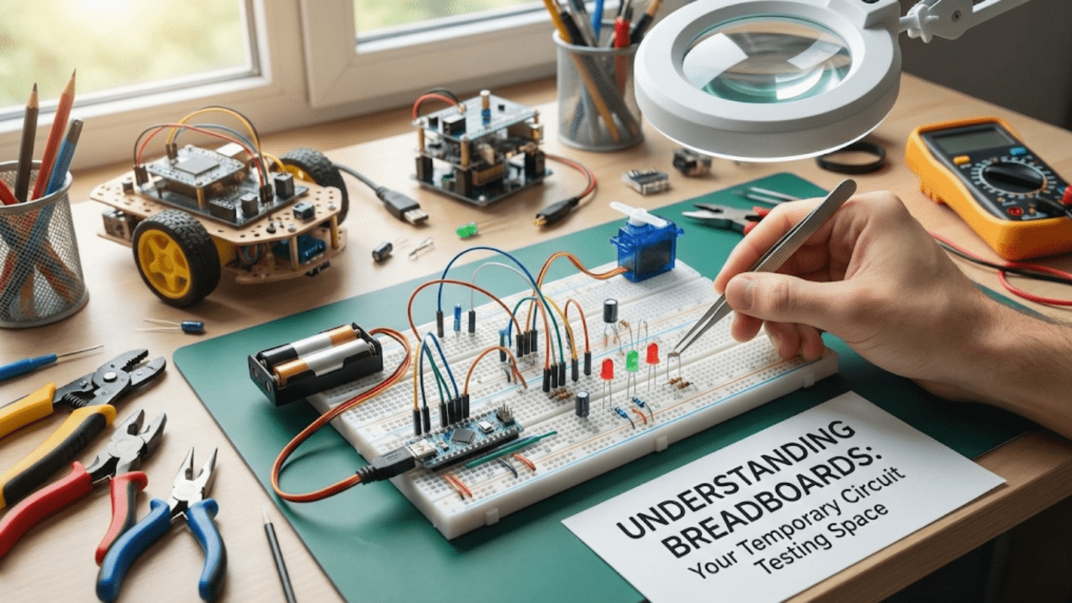
Every circuit in a robot starts somewhere. Before wires are soldered, before a custom PCB is ordered, before a circuit is declared finished, it almost always spends time on a breadboard — plugged in, tested, modified, pulled apart, and rebuilt in improved form. The breadboard is where robot electronics happen before they graduate to permanent form.
If you’ve never used a breadboard before, the grid of holes can look confusing — how do you know which holes connect to which? Why are some holes in rows and others in columns? Why does the power rail seem to be separate from the main grid? These questions have precise, logical answers that, once understood, make the breadboard feel completely intuitive.
If you’ve used a breadboard a little but encountered mysterious failures — components that seem connected but aren’t, circuits that work sometimes and not others, voltage readings that don’t make sense — this article addresses the specific failure modes and misunderstandings that cause them.
This complete guide covers everything: how breadboards are built internally, how to read their layout correctly, how to place components and route wires cleanly, the most common mistakes beginners make and exactly why those mistakes happen, and how to approach building complex circuits systematically on a breadboard.
What Is a Breadboard? History and Purpose
The name “breadboard” comes from the literal wooden cutting boards used in the early days of electronics experimentation — engineers would drive nails or screws into a wooden board and connect components and wires around them. This was the original solderless prototyping method before dedicated breadboard hardware existed.
Modern breadboards replaced this technique with spring-loaded metal clips inside a plastic housing. A wire or component lead pushed into a hole deflects the spring clip and makes contact. Pull it out and the clip springs back to its original position, ready for the next component. No heat, no solder, no chemical flux, no damage to the component or the board itself.
The key value proposition of a breadboard: you can try a circuit in minutes, find what’s wrong, change a component value, reroute a connection, and try again — without any of the time and permanence cost of soldering. For learning, experimenting, and prototyping in robotics, there is no faster or more accessible tool.
Internal Structure: How Breadboard Connections Actually Work
The most important thing to understand about a breadboard is its internal connection pattern. This determines which holes are electrically connected to each other — and misunderstanding this is the source of most breadboard failures.
The Main Component Area: Rows of Five
The central section of a breadboard is divided into two halves by a gap running down the middle. Each half consists of numbered rows, where each row contains five holes (labeled a–e on one side and f–j on the other). All five holes in a single row on one side of the gap are internally connected:
Breadboard internal connections (top view):

     a  b  c  d  e       f  g  h  i  j
  ┌──┬──┬──┬──┬──┬─ GAP ─┬──┬──┬──┬──┬──┐
1 │○ │○ │○ │○ │○  │       │○ │○ │○ │○ │○ │
  │  └──┴──┴──┘  │       │  └──┴──┴──┘  │
  │ Connected!   │       │  Connected!  │
2 │○ │○ │○ │○ │○  │       │○ │○ │○ │○ │○ │
  │  └──┴──┴──┘  │       │  └──┴──┴──┘  │
3 │○ │○ │○ │○ │○  │       │○ │○ │○ │○ │○ │
  └──┴──┴──┴──┴──┴───────┴──┴──┴──┴──┴──┘

Row 1a, 1b, 1c, 1d, 1e → all connected to each other
Row 1f, 1g, 1h, 1i, 1j → all connected to each other
Row 1e and Row 1f → NOT connected (separated by the gap)

Row 1a–e and Row 2a–e → NOT connected (different rows)The gap down the middle is not just physical — it’s electrical. The two halves of every numbered row are independent circuits. This gap is specifically sized to fit dual in-line package (DIP) integrated circuits, which have legs along both sides. When a DIP IC straddles the gap, each leg lands in a separate half-row on each side, and the gap ensures the legs on one side aren’t connected to the legs on the other.
The Power Rails: Columns Running the Full Length
Along the top and bottom edges (and sometimes along both sides in larger breadboards) run two power rails. Unlike the component area, these are organized as vertical columns rather than horizontal rows:
Power rail connections:

+ ○ ○ ○ ○ ○ ○ ○ ○ ○ ○ ○ ○ ○ ○ ○ ○ ○ ○ ○ ○
  ↑ All connected along the entire column
- ○ ○ ○ ○ ○ ○ ○ ○ ○ ○ ○ ○ ○ ○ ○ ○ ○ ○ ○ ○
↑ All connected along the entire columnThe red (+) rail is typically connected to VCC (5V, 3.3V, or whatever your supply voltage is). The blue (−) rail is connected to GND. Once you connect your power supply to these rails, every component in the main area can access power by running a short wire to the nearest rail hole.
Important caveat on longer breadboards: Some 830-hole full-size breadboards have a physical break in the power rails at the midpoint — the rail is actually two separate sections, each running half the length of the board. This break is not always obvious. If components connected to opposite ends of a power rail are getting different voltages (or no voltage), this hidden break is a likely culprit. Test continuity between the ends with a multimeter if in doubt.
Visualizing the Complete Connection Map
Understanding the complete connection map is essential. Here’s a summary:
BREADBOARD CONNECTION RULES:
━━━━━━━━━━━━━━━━━━━━━━━━━━━━━━━━━━━━━━━━
✓ Holes in the SAME ROW, SAME HALF → connected
✗ Holes in the SAME ROW, DIFFERENT HALF (across gap) → NOT connected
✗ Holes in DIFFERENT ROWS → NOT connected
✓ Holes in the SAME POWER RAIL COLUMN → connected (entire length*)
✗ Holes in DIFFERENT POWER RAIL COLUMNS → NOT connected
   * except at midpoint break on some full-size boards
━━━━━━━━━━━━━━━━━━━━━━━━━━━━━━━━━━━━━━━━Breadboard Sizes and Types
Breadboards come in several sizes, each suited to different project scales:
Half-Size (400-Hole) Breadboard
Dimensions: Approximately 83mm × 55mm Rows: ~30 numbered rows per side Power rails: Two rails along one or both edges Best for: Small single-IC circuits, sensor testing, quick experiments with one or two ICs
This is the size that comes with most beginner starter kits. It’s large enough for simple Arduino sensor circuits but gets crowded with multiple ICs, power regulators, and sensor breakout boards. Perfect for learning breadboard use.
Full-Size (830-Hole) Breadboard
Dimensions: Approximately 167mm × 55mm Rows: ~63 numbered rows per side Power rails: Four rails (two per edge) Best for: Arduino + multiple sensors, H-bridge motor control circuits, multi-IC projects
The standard for intermediate robotics prototyping. Large enough for an Arduino Nano or Pro Mini with sensors, motor driver, and support components. The 830-hole board is the workhorse of hobby electronics.
Mini Breadboard (170-Hole)
Dimensions: Approximately 45mm × 35mm Rows: ~17 rows per side Power rails: None or minimal Best for: Tiny single-IC breakout testing, embedded in a robot alongside a microcontroller
Mini breadboards sometimes have adhesive backing and can be stuck directly to a robot chassis for in-situ testing. Useful for testing individual sensor modules.
Breadboard Sets with Binding Posts
Some breadboard platforms include terminal posts for connecting power supplies and include provisions for mounting the breadboard in an enclosure. These are convenient for bench use but less important for robotics where the breadboard is typically powered by a microcontroller.
Setting Up a Breadboard for Robotics
Before placing a single component, a disciplined setup procedure prevents power problems and makes the circuit easier to debug.
Step 1: Identify the Connection Pattern
Orient the breadboard with the numbers increasing left-to-right (or as convenient for your working style) and verify you understand which holes connect. The lettered columns (a–e, f–j) run horizontally; the numbered rows run vertically. The power rails run the full board length.
Step 2: Connect Power and Ground to the Rails
Run a wire from your power source’s positive terminal to the red (+) rail. Run a wire from ground to the blue (−) rail. If using an Arduino as the power source:
Arduino 5V pin  →  Breadboard + rail (red)
Arduino GND pin →  Breadboard - rail (blue)

For 3.3V components:
Arduino 3.3V pin → separate breadboard + rail or dedicated column
Keep 3.3V and 5V rails clearly labeled to prevent mixingUse red wire for VCC connections and black wire for GND connections throughout the build. This color convention is universal and makes circuit reading much easier.
Step 3: Connect Both Power Rails (If Using Both Sides)
Full-size breadboards have power rails on both top and bottom edges. Bridge both + rails together and both − rails together with short wires:
Top + rail ──── short wire ──── Bottom + rail
Top − rail ──── short wire ──── Bottom − railThis makes power accessible from both edges without long wires crossing the component area. Many beginners skip this step and then wonder why a component connected to the bottom rail doesn’t get power when they connected the supply to the top rail.
Step 4: Verify Power Before Placing Components
With power connected and the circuit otherwise empty, measure voltage between the + and − rails with a multimeter. You should read exactly your supply voltage. This catches power wiring errors before any components are at risk.
Placing Components Correctly
With power confirmed, component placement begins. There are specific rules that make breadboard circuits reliable and readable.
Resistors and Capacitors (Passive Components)
Through-hole resistors and capacitors have two wire leads. The lead spacing determines how they must be placed:
Across rows: Place one lead in one row and the other lead in a different row. The rows are not connected, so the component bridges two separate nodes in your circuit. This is the standard orientation for resistors and capacitors.
Correct resistor placement:
Row 5: one lead in 5a (connected to the rest of 5a–5e)
Row 7: other lead in 7a (connected to the rest of 7a–7e)
Rows 5 and 7 are NOT connected — the resistor is the only path between them.

Incorrect: both leads in the same row
Row 5: both leads in 5a and 5b
These holes are connected! The resistor is short-circuited.Lead bending: Resistor leads often need to be bent to fit the row spacing. Use needle-nose pliers to make clean right-angle bends. Bent leads are more secure in the breadboard and less likely to pull out when nearby components are adjusted.
Integrated Circuits (ICs)
DIP (Dual In-line Package) ICs are the standard through-hole package for chips on a breadboard. They straddle the center gap:
DIP IC placement (8-pin example):

       a  b  c  d  e       f  g  h  i  j
    ┌──┬──┬──┬──┬──┬─ GAP ─┬──┬──┬──┬──┬──┐
 1  │  │  │  │  │○ │       │○ │  │  │  │  │ ← Pin 8
 2  │  │  │  │  │○ │       │○ │  │  │  │  │ ← Pin 7
 3  │  │  │  │  │○ │       │○ │  │  │  │  │ ← Pin 6
 4  │  │  │  │  │○ │       │○ │  │  │  │  │ ← Pin 5
    │                                       │
    IC body spans the gap (pins face down)
    │                                       │
 5  │  │  │  │  │○ │       │○ │  │  │  │  │ ← Pin 4
 6  │  │  │  │  │○ │       │○ │  │  │  │  │ ← Pin 3
 7  │  │  │  │  │○ │       │○ │  │  │  │  │ ← Pin 2
 8  │  │  │  │  │○ │       │○ │  │  │  │  │ ← Pin 1
    └──┴──┴──┴──┴──┴───────┴──┴──┴──┴──┴──┘

Pins 1–4 occupy column e (rows 5–8) — each in its own row
Pins 5–8 occupy column f (rows 5–8) — each in its own row
Pin 1 (row 8, column e) is NOT connected to Pin 8 (row 1, column f) — different rows AND different sides of gapNotch or dot orientation: DIP ICs have a notch or circle at one end to mark Pin 1. Always orient the IC with Pin 1 in a consistent position (usually upper-left when the IC is placed horizontally). This makes referring to a pinout diagram straightforward.
Inserting DIP ICs: The pins are often slightly too wide to fit without bending. Place the IC on a flat surface and gently press both rows of pins against the surface to bend them inward slightly (approximately 5–10°) until they’re parallel. Then align with the breadboard holes and press straight down with even pressure. Never rock the IC side-to-side or you’ll bend individual pins.
Jumper Wires
Jumper wires connect between rows, between a row and a power rail, and between separate breadboards. Quality breadboard jumper wires have firm male pins that make secure contact; cheap wires with loose pins are a primary source of intermittent breadboard connections.
Wire routing conventions:
- Red wires: VCC / positive supply
- Black wires: GND
- Other colors: signal wires (use a consistent scheme — e.g., yellow for analog signals, blue for digital, orange for PWM)
- Keep wires as short as practical — long wires that loop over the board are harder to trace and can catch on components
- Route wires around components rather than over them — wires over components make it impossible to read component values and harder to remove individual components
Sensor Breakout Boards
Many robotics sensors come on breakout boards with 0.1″ (2.54mm) header pins that plug directly into breadboards. These boards straddle one or both halves of the breadboard just like DIP ICs. When placing a breakout board:
Typical breakout board placement:

Left half of rows: one column of pins (VCC, GND, SDA, SCL, etc.)
                   Each pin in its own row
Right half of rows: blank (breakout board occupies only one column)

Then connect to each pin's row:
  Row where VCC pin sits → connect to + rail
  Row where GND pin sits → connect to − rail
  Row where SDA sits → connect to Arduino SDA pin's row
etc.Wiring an Arduino to a Breadboard
For the most common robotics prototyping setup — an Arduino connected to sensors and components on a breadboard — the connection approach matters for reliability and clarity.
Using an Arduino Nano or Pro Mini (Breadboard-Native)
Arduino Nano and Pro Mini boards are specifically designed for breadboard use, with 0.1″ header pins that plug directly into the breadboard. Place the Nano straddling the center gap, with digital and analog pins on one side and power/GND pins accessible on the other:
Arduino Nano on full-size breadboard:

Position the Nano in the center of the board
Nano's left pins → column e (rows 1–15 approximately)
Nano's right pins → column f (same rows)

The gap between e and f means each Nano pin occupies its own row on each side,
giving you 4 free connection holes (a–d or g–j) in each row to connect components.

Connect:
  Nano 5V pin row → + rail (red wire, any column in that row)
  Nano GND pin row → − rail (black wire)
Nano 3.3V pin row → separate labeled column or second railUsing an Arduino Uno (External Board)
The Arduino Uno is too large to mount on a breadboard directly, but connects via jumper wires:
Arduino Uno wiring to breadboard:

Arduino pin → Jumper wire → Breadboard row
VCC (5V)   → Red wire   → Red (+) rail
GND        → Black wire → Blue (−) rail

Digital pin 2 → Yellow wire → Row 10, column a
(remaining connections in row 10: columns b–e available for circuit components)Keep jumper wires from the Uno neatly bundled and labeled; crossing wires from an Uno to a breadboard quickly become a tangle that obscures the circuit.
Common Breadboard Mistakes and How to Avoid Them
Mistake 1: Component Leads in the Wrong Rows (Most Common)
The most frequent breadboard error is placing a component’s two leads in the same row rather than different rows, accidentally short-circuiting it. A resistor with both leads in row 5 doesn’t resist anything — the row connects them with near-zero resistance.
Prevention: Before inserting each component, count the row numbers for each lead. Confirm they are different rows and on the same side of the center gap.
Mistake 2: Not Bridging the Center Gap When Intended
Some circuits require connecting the two halves of a row (e.g., a wire connecting a component on the left half to a component on the right half of the same numbered row). The center gap breaks this connection — you need an explicit jumper wire across the gap.
Prevention: When your circuit diagram shows a connection that crosses the center area, use a jumper wire even if the row numbers are the same.
Mistake 3: Disconnected Power Rails
Forgetting to connect both top and bottom power rails together, or connecting power only to one rail and using a component on the other.
Prevention: At the start of every build, bridge both + rails together and both − rails together as a habit, regardless of whether you think you’ll need both sides.
Mistake 4: Hidden Rail Break on Full-Size Boards
As mentioned, some full-size breadboards have a break in the power rail at the midpoint. Components on opposite sides of this break are not connected even though they appear to be on the same rail.
Prevention: When using a full-size breadboard for the first time, test continuity between the ends of each rail with a multimeter. Add a jumper across any break you find.
Mistake 5: Loose or Partially Inserted Wires
A wire that is only partially inserted into a breadboard hole makes intermittent contact. The circuit works when you’re not touching it, fails when the board vibrates (in a robot), and may work again if you press the wire down. These faults are notoriously difficult to find because they look correct visually.
Prevention: When inserting wires, push firmly until you feel resistance. Give each wire a gentle tug after insertion — a well-seated wire should not pull out without deliberate force. Use quality jumper wires with firm pins, not cheap wires that feel loose.
Mistake 6: Powering the Wrong Voltage Rail
In mixed 5V/3.3V circuits, accidentally connecting a 5V supply to the 3.3V rail (or connecting a 3.3V sensor to the 5V rail) immediately damages 3.3V components. The 5V exceeds most 3.3V components’ absolute maximum input voltage.
Prevention: Clearly label rails with masking tape and a marker: “5V” and “3.3V” and “GND.” Use consistent wire colors — one color for 5V, a different color for 3.3V. Before powering on, trace each rail back to its source.
Mistake 7: Using the Breadboard in a Moving Robot
Breadboards are designed for bench prototyping, not for installation in moving robots. Vibration loosens component leads and wires, creating intermittent connections that are nearly impossible to diagnose while the robot is running.
Prevention: Keep breadboards for the design/test phase only. Once a circuit is verified working on the breadboard, transfer it to perfboard (soldered) or a custom PCB for installation in the robot. If you must temporarily test a circuit in a moving robot, secure the breadboard firmly and add strain relief to all wire connections.
Building Complex Circuits Systematically
Building a complex circuit — an H-bridge motor driver, a sensor conditioning circuit, a voltage divider network — on a breadboard becomes much easier with a systematic approach.
Step 1: Draw or Print the Schematic First
Never start placing components on a breadboard without a clear schematic. The schematic shows which node each component connects to; the breadboard is just the physical implementation of those connections.
Step 2: Identify the Nodes
A “node” is a set of points in a circuit that are electrically connected. In a schematic, every wire segment that connects without interruption is one node. On the breadboard, each node corresponds to one or more connected rows (or a power rail).
Map each schematic node to a specific breadboard row:
Example: LED circuit mapping
Node 1: Arduino pin 13 output → Row 10, column a–e
Node 2: LED anode (connecting resistor to LED) → Row 12, column a–e
Node 3: GND → Blue (−) power rail

Placement:
- Wire from Arduino pin 13 to Row 10, column a
- Resistor: one lead in Row 10, other lead in Row 12
- LED anode in Row 12 (same row as resistor output)
- LED cathode in Row 14
- Wire from Row 14 to GND railStep 3: Place Power Connections and ICs First
Place the largest components first: ICs (which constrain row positions), power distribution connections, and any large capacitors. Then fill in the smaller components around them.
Step 4: Add Components Section by Section
Build the circuit one functional block at a time. After each block, verify it works before adding the next. Debugging a complete circuit built all at once is much harder than catching problems block by block.
Step 5: Verify With Multimeter Before Powering
Before applying power to a new breadboard circuit, do a quick continuity check:
- Verify VCC rail doesn’t have continuity to GND rail (would indicate a short)
- Verify IC power pins are connected to appropriate rails
- Check a few critical connections for continuity
This catches wiring errors that would otherwise damage components or produce confusing behavior.
Breadboard Prototyping Tips for Specific Robotics Circuits
LED Indicator Test Circuit
The simplest useful robotics circuit — a LED connected to a microcontroller output pin — is the perfect first breadboard build:
Arduino Pin 13 → Row 1, column a
220Ω resistor  → leads in Row 1 (column b) and Row 3 (column b)
LED anode      → Row 3, column c
LED cathode    → Row 5, column c
GND jumper     → Row 5, column d → GND rail

Schematic:
[Arduino Pin 13]---[220Ω]---[LED+]---[LED-]---[GND]If the LED doesn’t light: check that the LED is not inserted backwards (LEDs are polarized — longer lead is anode/positive). Check the resistor is spanning two different rows. Check connections to GND rail.
Voltage Divider for Sensor Reading
Battery (+) → Row 1, column a
10kΩ resistor → leads in Row 1 (column b) and Row 4 (column b)
4.7kΩ resistor → leads in Row 4 (column c) and Row 7 (column c)
GND jumper → Row 7, column d → GND rail
Arduino A0 → Row 4, column d (mid-point between resistors)

Row 4 is the voltage divider output node:
10kΩ resistor, 4.7kΩ resistor, AND Arduino A0 all share Row 4 = connectedI2C Sensor Module
Sensor VCC pin → Row 1, column f → +3.3V rail
Sensor GND pin → Row 2, column f → GND rail
Sensor SDA pin → Row 3, column f → Arduino SDA row (Row 3, column a)
Sensor SCL pin → Row 4, column f → Arduino SCL row (Row 4, column a)
4.7kΩ pull-up on SDA → Row 3 (b) to +3.3V rail
4.7kΩ pull-up on SCL → Row 4 (b) to +3.3V railWhen to Graduate from Breadboard to Permanent Circuit
Breadboards are excellent for prototyping but have real limitations that make them unsuitable for permanent or operating-in-robot use:
- Unreliable in vibration: Component leads and jumper wires loosen and create intermittent connections
- Current limits: Breadboard contact resistance (typically 0.1–0.5Ω per contact) causes voltage drop in high-current circuits; not suitable for motor power paths
- No strain relief: Wires connected to motors, batteries, and external sensors get tugged and pulled, eventually disconnecting
- Bulky: A breadboard circuit takes much more space than a soldered equivalent
The right time to move from breadboard to permanent form is when:
- The circuit works correctly and reliably for multiple test sessions
- You’ve stopped making changes to the design
- The circuit needs to be installed in the robot for actual operation
The next article in this series covers exactly this transition — from working breadboard prototype to a permanent soldered circuit, using perfboard and other prototyping methods that bridge the gap between breadboard and custom PCB.
Summary
The breadboard is the most important tool in the robotics builder’s prototyping toolkit — it transforms circuit building from a permanent, component-risking process into a rapid, reversible, iterative one. Understanding its internal connection pattern (rows of five in the component area, full-length columns in the power rails) is the key to using it correctly and avoiding the connection errors that cause most breadboard failures.
The most common mistakes — placing both leads of a component in the same row, forgetting to bridge power rails, using partially inserted wires — all have the same root cause: not fully internalizing the internal connection map before building. Once that map is understood intuitively, breadboard circuits become easy to construct, easy to read, and easy to debug.
Build on the breadboard first, verify thoroughly, then transfer to a permanent form. This workflow — prototype on breadboard, validate, then commit to solder — is how reliable robot electronics are built, and the breadboard is where that process begins.
The next article covers the transition from breadboard prototype to permanent circuit: the tools, materials, and techniques for moving from a working breadboard design to a soldered perfboard or stripboard circuit that is reliable enough to install permanently in a robot.
Debugging Breadboard Circuits: A Systematic Approach
Even experienced electronics builders encounter breadboard circuits that don’t work on the first try. The key is a systematic debugging methodology that isolates the problem quickly rather than randomly poking at things hoping something changes.
The Four-Step Debugging Process
Step 1: Power check. Before touching any components, measure the supply voltage between the + and − rails. Should read exactly your supply voltage (5.0V, 3.3V, etc.). If it reads zero or an unexpected value, the power wiring is the problem — fix this before anything else. A circuit that appears not to work but has the wrong supply voltage is always a power problem first.
Step 2: Component orientation check. Many components are polarized — LEDs, electrolytic capacitors, diodes, ICs all have a defined orientation that must be correct. Walk through every polarized component in your circuit and verify orientation against the schematic:
- LED: longer lead (anode) to the more positive voltage
- Electrolytic capacitor: longer lead (positive) to more positive voltage; white stripe on negative lead
- Diode: cathode (banded end) to the more negative side
- IC: notch or dot marking Pin 1 in the correct position
Step 3: Connection verification. For each wire and component in the circuit, trace the physical connection on the breadboard and confirm it matches the schematic:
- This wire goes from row X to the + rail — correct?
- This resistor spans from row Y to row Z — is that what the schematic shows?
- Does this IC’s power pin row connect to the correct supply rail?
Use the multimeter’s continuity mode (beeps when touching two connected points) to verify critical connections without relying on visual inspection alone.
Step 4: Signal tracing. If power and components check out, trace the signal through the circuit with a multimeter in voltage mode, following the path from input to output:
- At the input pin: correct signal present? (voltage level as expected)
- After the first component: voltage changed as expected?
- Continue to output: where does the expected behavior stop?
The point where the signal diverges from expectation is where the fault lies.
Using the Multimeter for Breadboard Debugging
Multimeter modes for breadboard debugging:

DC Voltage mode:
  Measure: between any two nodes to see voltage difference
  Useful for: verifying supply rails, checking signal levels,
              confirming voltage divider outputs

Continuity mode (beep):
  Touch: two points that should be connected
  Beep = connected, no beep = not connected
  Useful for: verifying a wire connects where expected,
              checking that two component leads share a row,
              finding broken connections inside breadboard
  WARNING: Use only on unpowered circuits! Continuity mode
           injects a small current — it can damage powered components.

Resistance mode:
  Measure: across a component in isolation (remove from circuit first)
Useful for: verifying resistor values, checking for open/shorted componentsThe Substitution Method
When a circuit almost works but one function is wrong, substituting a known-good component for the suspected faulty one is the fastest diagnostic technique. Suspect a particular resistor has the wrong value? Swap it with one you’ve measured with a multimeter. Suspect an LED is burned out? Try a different one. Suspect the IC is damaged? Try a fresh one.
Substitution is particularly valuable for components that can look physically identical while being electrically different (resistors of similar value) or components that can be invisibly damaged (ICs that got ESD damage or overheating).
Reading Breadboard-Based Circuit Diagrams
Many robotics tutorials show circuit diagrams as “breadboard views” rather than traditional schematics — an illustration showing the actual breadboard with components placed visually. Learning to read both formats bridges understanding between the tutorial and the real breadboard in front of you.
Breadboard View Diagrams
Software tools like Fritzing generate breadboard view diagrams that show exactly which holes components and wires occupy. These are beginner-friendly but can become cluttered with complex circuits. When following a breadboard view diagram:
- Identify the power connections first — which rail is VCC, which is GND
- Place the microcontroller or main IC in the position shown
- Work outward from the microcontroller, one component at a time
- Check your physical placement against the diagram after every three or four components — catching errors early saves time
Schematic to Breadboard Translation
When a tutorial shows only a schematic (the traditional electrical diagram with symbols rather than physical representations), you need to translate it to a breadboard layout yourself. This is the more valuable skill:
Schematic translation process:

1. List all nodes in the schematic (all named junctions)
2. Assign each node to a breadboard location:
   - VCC nodes → + power rail
   - GND nodes → − power rail
   - Each signal node → a unique row number
3. Place components based on which two nodes they connect
   (component goes between its two assigned rows)
4. Place wires for long-distance connections between rows
   and between component rows and power rails

Example translation: LED blink circuit

Schematic nodes:
  NODE_A = Arduino D13 output
  NODE_B = Resistor-to-LED junction
  GND    = Ground

NODE_A → Row 5 (connected to Arduino D13)
NODE_B → Row 8 (mid-point, no specific requirement)
GND    → GND rail

Placement:
  220Ω resistor: Row 5 (one lead) to Row 8 (other lead)
  LED anode: Row 8
LED cathode: GND rail (direct or via Row 10 jumper to GND rail)This translation skill — going from abstract schematic to physical breadboard layout — is what enables you to implement any circuit design, not just copy tutorials that show breadboard views. It’s one of the most valuable practical skills in robotics electronics.
Breadboard Care and Maintenance
Breadboards last for years with minimal maintenance, but a few habits extend their reliable life:
Avoid bending component leads inside breadboard holes. When removing components, pull straight out — rocking components side to side bends both the component lead and the breadboard clip. Eventually bent clips lose their spring tension and stop making reliable contact.
Remove components between sessions. Leaving components inserted for weeks or months can cause the spring clips to take a “set” — they stop springing back fully. Clean your breadboard after each project.
Clean with isopropyl alcohol if contacts become oxidized. Over time, especially in humid environments, breadboard contact clips can oxidize and become resistive. A few drops of 90%+ isopropyl alcohol dripped into the holes, allowed to work for a minute, and blown out with compressed air can restore conductivity.
Replace breadboards that develop unreliable contacts. Breadboards are consumables — eventually the clip springs fatigue and contacts become unreliable. If a breadboard frequently produces intermittent connections even with freshly inserted, straight-leaded components, it’s time to replace it. Quality breadboards (Elegoo, Adafruit, SparkFun) last longer than the cheapest alternatives.
Store with a cover or upside-down. Dust and debris in breadboard holes causes poor contact. Store breadboards in the original packaging, in a zip-lock bag, or upside-down to keep holes clear.
Breadboards and Electrostatic Discharge (ESD) Sensitivity
Some components — particularly MOSFETs, CMOS ICs, and certain sensors — are sensitive to electrostatic discharge. Human body static electricity can carry thousands of volts briefly and damage these components on contact.
On a breadboard, the plastic housing provides no ESD protection. Best practices when handling ESD-sensitive components:
- Touch a grounded metal object (a metal water pipe, the ground pin of an unplugged power supply) before handling sensitive components to discharge body static
- Handle ICs by their body, not their pins — fingers on pins directly transfer any static charge to the gate
- In dry winter environments (low humidity increases static buildup), consider an anti-static wrist strap — an inexpensive tool ($5–10) that keeps you continuously grounded through a high-resistance cord
Most common hobbyist components (through-hole resistors, capacitors, LEDs, standard Arduino sensors) are not particularly ESD-sensitive. The caution increases for bare MOSFET transistors, precision analog ICs, and advanced communication chips.