Pull-up and pull-down resistors are components that connect a digital input pin to a known voltage level — VCC for pull-up resistors (connecting the pin to the positive supply through a resistor), or GND for pull-down resistors (connecting the pin to ground through a resistor) — to ensure the pin reads a definite HIGH or LOW state when no active signal is driving it, preventing the erratic and unpredictable behavior of a “floating” input that can randomly read either state due to stray electrical noise. They are essential in button and switch circuits, I2C communication buses, open-collector and open-drain sensor outputs, and any digital input that is not always actively driven to a known voltage.
Introduction
You add a button to your robot. You write code that reads the button pin and does something when it’s pressed. You upload the code and test it. The robot behaves as if the button is being pressed repeatedly even when you’re not touching it — then it stops responding when you do press it. You check the wiring and it looks correct. You re-upload the code. Same problem. The button works maybe one time in five, randomly, seemingly independently of whether you’re actually pressing anything.
This is a floating input, and a pull-up or pull-down resistor is the fix. It is one of the most common beginner problems in digital electronics, appearing in buttons, switches, limit switches, open-collector sensors, I2C buses, UART lines, and dozens of other circuits. Once you understand why floating inputs cause problems and how pull resistors solve them, you’ll recognize the need for them immediately in any new circuit you build.
This article gives you the complete understanding: what floating inputs actually are at a physical level, how pull-up and pull-down resistors work, when each type is appropriate, how to choose the right resistance value, how to use the microcontroller’s built-in pull resistors, and the specific requirements for I2C and other communication buses that depend on pull resistors for correct operation.
The Floating Input Problem: What Actually Happens
To understand why pull resistors are necessary, you need to understand what a “floating” or “high-impedance” input actually is at a physical and electrical level.
The Physics of a Floating Pin
A microcontroller’s digital input pin is connected to the gate of a MOSFET transistor inside the chip. The gate of a MOSFET is insulated — it doesn’t draw current in normal operation. This is what makes it useful (it doesn’t load the signal source), but it also means the gate is essentially a tiny capacitor (perhaps 1–10 picofarads) connected to nothing when no signal source is driving it.
A capacitor with no defined charge path will charge to whatever voltage it happens to find through any available path — including stray electromagnetic fields in the environment (radio frequency interference from WiFi, motors, fluorescent lights, and other sources), capacitive coupling from adjacent wires, and even the small amount of leakage current through the insulation on the circuit board.
The voltage a floating MOSFET gate settles at is therefore determined entirely by these random, varying influences. It might sit near VCC, near GND, or anywhere in between — and it changes moment to moment as the electromagnetic environment changes.
How Microcontrollers Interpret Floating Voltages
Digital logic defines two valid input states: HIGH (above the logic HIGH threshold, approximately 0.7 × VCC for CMOS logic) and LOW (below the logic LOW threshold, approximately 0.3 × VCC). Any voltage in between these thresholds is in the “undefined” region — neither a valid HIGH nor a valid LOW.
When a floating pin’s voltage wanders into the defined HIGH region, the microcontroller reads it as HIGH. When it wanders into the defined LOW region, it reads it as LOW. When it’s in the undefined region, the input buffer may oscillate rapidly between HIGH and LOW interpretations as tiny voltage fluctuations push it back and forth across the threshold.
The result: the digitalRead() function returns completely unpredictable values — not because anything is broken, but because the pin genuinely has no defined state to read. A button connected to a floating input appears to press itself at random, a limit switch triggers at random, and a communication line looks like it’s receiving garbage data.
Floating pin behavior illustration:

Time →  ....continuous....
Actual pin voltage: ~2.3V → ~2.7V → ~2.1V → ~3.1V → ~1.9V → ~2.5V
VCC = 5V, HIGH threshold = 3.5V, LOW threshold = 1.5V

Reading:             LOW       LOW      LOW      LOW     LOW      LOW

...then motor starts nearby, coupling noise onto the wire...

Pin voltage: ~2.3V → ~3.8V → ~1.2V → ~4.1V → ~0.8V → ~3.9V
Reading:      LOW     HIGH    LOW    HIGH    LOW    HIGH
↑ apparently "pressed" when motor ranThis is exactly the phantom button-press behavior that confuses beginners. The button isn’t broken. The code isn’t wrong. The pin is floating, and the motor’s electromagnetic noise is coupling enough voltage onto the unconnected input wire to push it into the HIGH region.
Pull-Up Resistors: Holding the Pin HIGH by Default
A pull-up resistor connects the input pin to VCC through a resistor. The resistor creates a weak connection to VCC — “weak” because a high-resistance path is easily overridden by an active signal.
How It Works
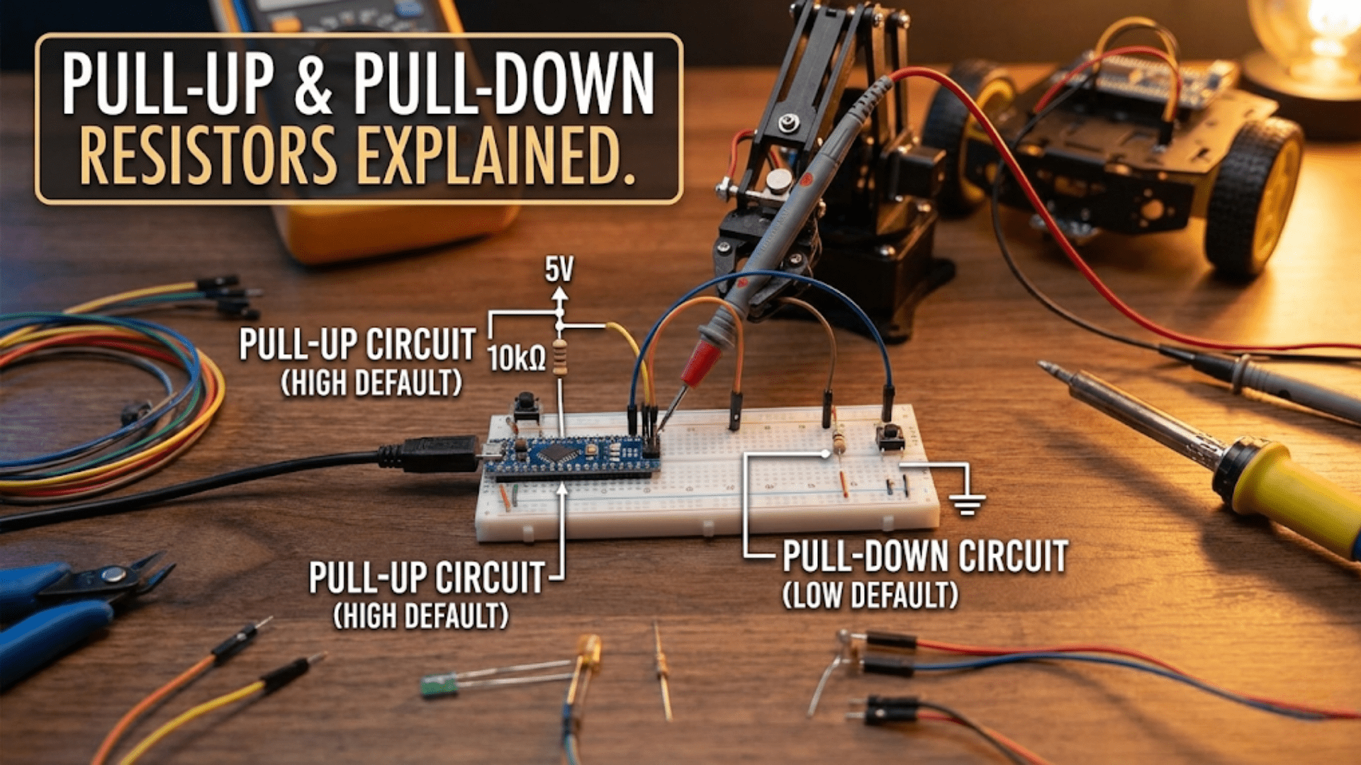
Pull-up circuit (button connecting pin to GND):

VCC ──────[R pull-up]──────┬──── Input pin (to microcontroller)
                           │
                         [Button]
                           │
                          GND

Button OPEN (not pressed):
- No current path to GND through the button
- Pull-up resistor connects pin weakly to VCC
- Pin voltage = VCC (typically 5V or 3.3V)
- digitalRead() = HIGH

Button CLOSED (pressed):
- Current flows: VCC → R → Pin → Button → GND
- Pin is now connected to GND through the low-resistance button
- Pin voltage ≈ 0V (GND wins over pull-up)
- digitalRead() = LOWThe key insight is that the pull-up resistor holds the pin at a known HIGH state when nothing else is driving it, but is “weak” enough (high resistance) that an active circuit driving the pin LOW can easily overcome it. The pin can be driven strongly to one state; the pull-up just ensures it has a defined state when nothing is driving it at all.
With a pull-up, a button press reads as LOW (the button connects the pin to GND, overriding the pull-up). This is called active-low logic — the event you’re detecting (button pressed) causes a LOW reading rather than a HIGH. Many robotics circuits use active-low logic for buttons and switches because it’s what pull-up resistors naturally produce.
// Pull-up resistor with button — active low logic
const int BUTTON_PIN = 7;

void setup() {
  pinMode(BUTTON_PIN, INPUT);  // External pull-up handles it
  Serial.begin(9600);
}

void loop() {
  int buttonState = digitalRead(BUTTON_PIN);

  if (buttonState == LOW) {
    // Button is PRESSED (pin pulled LOW by button to GND)
    Serial.println("Button pressed!");
  } else {
    // Button is NOT pressed (pin held HIGH by pull-up resistor)
    // This is the default/idle state
  }

  delay(50);
}Pull-Down Resistors: Holding the Pin LOW by Default
A pull-down resistor connects the input pin to GND through a resistor, holding it at LOW when nothing else drives it. The complementary case: a button connects the pin to VCC when pressed.
How It Works
Pull-down circuit (button connecting pin to VCC):

VCC ──────[Button]──────┬──── Input pin (to microcontroller)
                        │
                    [R pull-down]
                        │
                       GND

Button OPEN (not pressed):
- No current path to VCC through the button
- Pull-down resistor connects pin weakly to GND
- Pin voltage = 0V (GND)
- digitalRead() = LOW

Button CLOSED (pressed):
- Current flows: VCC → Button → Pin → R pull-down → GND
- VCC drives the pin strongly to HIGH
- Pin voltage ≈ VCC
- digitalRead() = HIGHWith a pull-down, a button press reads as HIGH. This is active-high logic — the event (button pressed) causes a HIGH reading. Some builders prefer this because it feels more intuitive: pressed = HIGH, released = LOW.
// Pull-down resistor with button — active high logic
const int BUTTON_PIN = 7;

void setup() {
  pinMode(BUTTON_PIN, INPUT);  // External pull-down handles it
  Serial.begin(9600);
}

void loop() {
  int buttonState = digitalRead(BUTTON_PIN);

  if (buttonState == HIGH) {
    // Button is PRESSED (pin driven HIGH by button to VCC)
    Serial.println("Button pressed!");
  } else {
    // Button is NOT pressed (pin held LOW by pull-down resistor)
  }

  delay(50);
}Pull-Up vs. Pull-Down: When to Choose Each
Choose pull-up when:
  ✓ Using the microcontroller's internal pull-up (saves external component)
  ✓ The sensor or switch connects to GND when active (common in limit switches)
  ✓ Using open-collector/open-drain outputs (they can only pull low, not high)
  ✓ The signal source is at a lower voltage than VCC (level-shifting concerns)
  ✓ I2C bus — always uses pull-ups, never pull-downs
  ✓ Buttons in most robotics applications (convention)

Choose pull-down when:
  ✓ The sensor or switch connects to VCC when active
  ✓ Active-high logic is more natural for the application
  ✓ The default state needs to be LOW (e.g., a "ready" signal that goes HIGH when ready)
✓ MOSFET gate inputs that must default to OFF (gate LOW = MOSFET off)In practice, pull-up resistors are far more common in robotics than pull-down resistors for two reasons: most switches and sensors (limit switches, encoders with open-collector outputs, most communication buses) pull their output LOW when active, and microcontrollers have built-in pull-up resistors but typically not built-in pull-downs.
Internal Pull-Up Resistors: The Built-In Solution
Most modern microcontrollers — including all Arduino-compatible chips — have built-in pull-up resistors on their digital input pins that can be enabled in software without any external component. This is one of the most useful features for robotics because it eliminates the need for an external resistor in most button and switch circuits.
Enabling Internal Pull-Ups on Arduino
// Method 1: Using INPUT_PULLUP in pinMode()
// This is the recommended modern approach (Arduino 1.0.1+)
pinMode(BUTTON_PIN, INPUT_PULLUP);

// With INPUT_PULLUP, a floating pin reads HIGH.
// A button connecting the pin to GND reads LOW.
// Same active-low logic as external pull-up.

// Method 2: Writing HIGH to a pin configured as INPUT (deprecated, still works)
pinMode(BUTTON_PIN, INPUT);
digitalWrite(BUTTON_PIN, HIGH);  // Enables internal pull-up on AVR chips
// This method is NOT recommended — use INPUT_PULLUP instead.
// Complete button example using internal pull-up
// No external resistor needed — just button connected between pin and GND
const int BUTTON_PIN = 2;
const int LED_PIN = 13;
void setup() {
pinMode(BUTTON_PIN, INPUT_PULLUP); // Enable internal pull-up
pinMode(LED_PIN, OUTPUT);
Serial.begin(9600);
}
void loop() {
// With INPUT_PULLUP: not pressed = HIGH, pressed = LOW
if (digitalRead(BUTTON_PIN) == LOW) {
digitalWrite(LED_PIN, HIGH);
Serial.println("Button pressed");
} else {
digitalWrite(LED_PIN, LOW);
}
delay(20);
}Internal Pull-Up Values and Limitations
The internal pull-up resistor on ATmega-based Arduinos (Uno, Nano, Mega) has a resistance of approximately 20–50kΩ (the datasheet specifies a range, not a precise value; typical is around 30–35kΩ). This value works well for buttons and switches, but it is not appropriate for all applications:
Internal pull-up: ~30kΩ (typical on Arduino AVR)

Too weak for:
  ✗ I2C bus — 30kΩ is too high; I2C requires 4.7kΩ or lower
  ✗ Long cable runs susceptible to capacitive loading
  ✗ Any application where the signal line capacitance is high
    (high capacitance + high pull-up resistance = slow rise time)

Appropriate for:
  ✓ Buttons and momentary switches at short distances
  ✓ Limit switches directly connected to the board
  ✓ Most simple digital sensor outputs

When to add external pull-up even if internal is available:
  → I2C/SPI/UART communication lines
  → Sensors at the end of long wires (>30cm)
→ Any input line that must respond quickly to state changesThe Raspberry Pi’s internal pull-up resistors are approximately 50–65kΩ — similar values with similar limitations. The ESP32 has configurable pull resistors of approximately 45kΩ.
Enabling Pull-Ups on Other Platforms
// Raspberry Pi (Python with RPi.GPIO)
import RPi.GPIO as GPIO
GPIO.setmode(GPIO.BCM)
GPIO.setup(17, GPIO.IN, pull_up_down=GPIO.PUD_UP)   # Pull-up on GPIO 17
GPIO.setup(18, GPIO.IN, pull_up_down=GPIO.PUD_DOWN) # Pull-down on GPIO 18
button_state = GPIO.input(17)  # LOW = pressed with pull-up

// ESP32 (Arduino IDE)
pinMode(BUTTON_PIN, INPUT_PULLUP);   // Same as Arduino
// or
pinMode(BUTTON_PIN, INPUT_PULLDOWN); // ESP32 also has internal pull-downs!

// STM32 (HAL library)
GPIO_InitStruct.Pull = GPIO_PULLUP;   // Pull-up
GPIO_InitStruct.Pull = GPIO_PULLDOWN; // Pull-down
GPIO_InitStruct.Pull = GPIO_NOPULL; // No pull (floating — use carefully)The ESP32 is notable for having both internal pull-up and pull-down resistors available in software — unusual in a microcontroller and convenient for applications where either polarity makes sense.
Choosing the Right Pull Resistor Value
The resistance value of a pull-up or pull-down resistor involves a trade-off between two competing requirements: low enough to reliably hold the pin at a defined level against noise and leakage, but high enough not to waste significant current or interfere with the driving circuit.
The Trade-Off
Lower resistance (e.g., 1kΩ pull-up):
  + More robust against noise — harder for induced voltages to overcome
  + Better signal integrity on long cable runs
  + Lower rise time on capacitive lines
  − Higher current when pin is driven LOW: I = VCC / R = 5V / 1kΩ = 5mA
    (continuous when button held pressed — significant for battery life)
  − May load sensitive signal sources (some open-collector devices have limited
    current sinking capability)

Higher resistance (e.g., 100kΩ pull-up):
  + Very low current: I = 5V / 100kΩ = 0.05mA (negligible)
  + Doesn't load signal sources
  − More susceptible to noise pickup on high-impedance input
  − Slow rise time with capacitive loads (long wires, connector capacitance)
− May not reliably overdrive stray leakage currents in high-humidity environmentsValue Selection by Application
Application                    Recommended value  Reasoning
────────────────────────────────────────────────────────────────────
Button/switch (short wire)     10kΩ               Good balance; 0.5mA when pressed
Button/switch (internal)       ~30kΩ (internal)   Convenient, fine for short connections
Limit switch (robot chassis)   4.7kΩ–10kΩ        Low enough for noise immunity
I2C SDA/SCL (up to 400kHz)     4.7kΩ              Standard; see I2C section below
I2C SDA/SCL (1MHz fast mode)   2.2kΩ–1kΩ         Lower for faster rise times
Open-collector sensor output   4.7kΩ–10kΩ        Match sensor's output current spec
UART TX/RX lines               Not usually needed  UART is actively driven both ways
Long wire run (>1 meter)       1kΩ–4.7kΩ         Low impedance fights noise and capacitance
MOSFET gate (default OFF)      10kΩ–100kΩ pull-down Minimal current; gate barely loads resistor
Reset pin (active low reset)   10kΩ               Hold MCU out of reset when not triggered
The 10kΩ value is the most common general-purpose choice because it balances current consumption (0.5mA at 5V when pulled to GND) against noise immunity, and it’s the value in every beginner starter kit. For most button and switch applications in robotics, 10kΩ is the right answer without further analysis.
I2C and Pull-Up Resistors: A Critical Requirement
I2C (Inter-Integrated Circuit) is one of the most widely used communication protocols in robotics — it’s how the Arduino talks to the MPU-6050 IMU, the BMP280 pressure sensor, the SSD1306 OLED display, and hundreds of other sensors and peripherals. I2C has a specific and mandatory pull-up resistor requirement that every robotics builder must understand.
Why I2C Requires Pull-Up Resistors
I2C is an open-drain (sometimes called open-collector) bus. Neither the master (Arduino) nor any slave device ever drives the SDA or SCL line HIGH. Instead, they only ever pull the line LOW (to GND) — or release it (stop pulling it LOW, leaving it floating).
The pull-up resistors are what drive the line back to HIGH when no device is pulling it LOW. Without pull-up resistors, the I2C lines have no way to return to HIGH after being pulled LOW — every I2C transaction would permanently pull the lines to GND and communication would fail entirely.
I2C line states:

Line HIGH: no device pulling LOW → pull-up resistor holds line at VCC
Line LOW:  a device (master or slave) actively pulling the pin to GND
           (the pull-up current flows through the device's output transistor)

Without pull-up:
  Line transitions LOW (device pulls it) → stays LOW forever
  The "HIGH" state cannot occur — I2C completely non-functional

With pull-up:
  Line goes LOW (device pulls it) → device releases → pull-up pulls line back HIGH
Normal I2C communication is possibleChoosing I2C Pull-Up Values
The I2C specification (NXP UM10204) defines the acceptable pull-up resistance range based on bus speed and capacitance:
I2C pull-up resistance constraints:

Minimum resistance (too low = too much current):
  Rmin = (VCC - VOL) / IOL
  where VOL = max LOW output voltage (0.4V), IOL = max sink current (3mA for standard)
  Rmin = (5V - 0.4V) / 3mA = 4.6V / 3mA = 1.53kΩ → use at least 1.5kΩ
  (For 3.3V systems: (3.3V - 0.4V) / 3mA = 967Ω → at least 1kΩ)

Maximum resistance (too high = too slow rise time):
  Rmax = rise_time / (0.8473 × Cbus)
  where rise_time = max allowable at that speed, Cbus = total bus capacitance

Standard mode (100kHz): max rise time 1000ns
  For 100pF bus capacitance: Rmax = 1000ns / (0.8473 × 100pF) ≈ 11.8kΩ
  → 4.7kΩ is safely within range for standard mode with typical cable length

Fast mode (400kHz): max rise time 300ns
  For 100pF: Rmax = 300ns / (0.8473 × 100pF) ≈ 3.54kΩ
  → Use 2.2kΩ for fast mode

Practical recommendations:
  Short connections (< 30cm, one or two devices):  4.7kΩ — always works
  Multiple devices or longer wires (30–100cm):      2.2kΩ
  Fast mode I2C (400kHz):                           2.2kΩ
Fast-plus mode (1MHz): 1kΩ–1.5kΩOne Set of Pull-Ups for the Whole Bus
A critical point beginners often miss: the I2C bus needs one set of pull-up resistors for the entire bus — not one per device. The SDA line has one pull-up, the SCL line has one pull-up. Adding pull-ups at each device creates parallel resistors that lower the effective resistance:
Three devices each with 4.7kΩ pull-ups on SDA:
Effective pull-up = 4.7kΩ / 3 = 1.57kΩ
→ Below minimum resistance for 3.3V systems
→ Excessive current sink required from every device when driving LOW

Correct approach: one 4.7kΩ on SDA, one 4.7kΩ on SCL — regardless
of how many devices are on the bus.

In practice: many I2C sensor breakout boards include their own pull-up
resistors (typically 4.7kΩ or 10kΩ) as a convenience for single-device use.
When multiple breakout boards share a bus, these per-board pull-ups combine
to create too-low effective resistance. The fix: remove (or lift one leg of)
the pull-up resistors on all but one breakout board, OR rely on the internal
pull-ups being disabled/absent on most boards in your collection.

Check your breakout board schematics — many have a solder jumper to
disconnect the on-board pull-ups for exactly this multi-device scenario.// Arduino I2C master setup — pull-ups handled externally
// The Arduino's Wire library enables I2C automatically
// Just ensure 4.7kΩ pull-ups are present on SDA (A4) and SCL (A5) on Uno
// or SDA (pin 20) and SCL (pin 21) on Mega
#include <Wire.h>
void setup() {
Wire.begin(); // Initialize I2C as master
Wire.setClock(400000); // 400kHz fast mode — requires 2.2kΩ pull-ups
Serial.begin(9600);
// Scan for I2C devices (useful for debugging pull-up issues)
Serial.println("Scanning I2C bus...");
int found = 0;
for (int addr = 1; addr < 127; addr++) {
Wire.beginTransmission(addr);
if (Wire.endTransmission() == 0) {
Serial.print("Device found at 0x");
Serial.println(addr, HEX);
found++;
}
}
if (found == 0) {
Serial.println("No devices found — check pull-up resistors on SDA/SCL!");
}
}If the I2C scanner finds no devices even though you know a sensor is connected and powered, missing or incorrect pull-up resistors are the most common cause after wiring errors. The scanner code is invaluable for diagnosing I2C pull-up problems.
Open-Collector and Open-Drain Outputs
Many sensors and logic devices use open-collector (in bipolar transistor circuits) or open-drain (in MOSFET circuits) outputs — output stages that can only actively pull the output LOW, never drive it HIGH. These outputs always require an external pull-up resistor to function:
Open-collector output behavior:

State = 0 (active): Transistor turns ON → output pulled to GND (LOW)
State = 1 (inactive): Transistor turns OFF → output floating (no drive)

Without pull-up: "1" state is FLOATING — undefined, susceptible to noise
With pull-up:    "1" state is VCC — defined HIGH

Common open-collector/open-drain devices:
- I2C bus (as described above)
- Many hall-effect sensors and encoders
- Comparator outputs (LM393, LM358 in comparator mode)
- Some temperature sensors (DS18B20 one-wire interface)
- Many relay driver outputs
- Interrupt outputs from many sensor ICs
- Level shifter circuits
Whenever a sensor datasheet says “open-drain output” or “open-collector output,” a pull-up resistor to the appropriate voltage is mandatory. The resistor value is typically specified in the sensor’s datasheet; if not, 4.7kΩ is a safe default.
// HC-SR04 alternative: some ultrasonic sensors use open-drain echo pin
// Similarly, DS18B20 temperature sensor uses single-wire open-drain protocol
// Requires external 4.7kΩ pull-up on the data line

// OneWire library example (DS18B20 thermometer)
// Hardware: DS18B20 data pin → Arduino pin 2
//           4.7kΩ pull-up between pin 2 and 5V (MANDATORY)

#include <OneWire.h>
#include <DallasTemperature.h>

const int ONE_WIRE_BUS = 2;
OneWire oneWire(ONE_WIRE_BUS);
DallasTemperature sensors(&oneWire);

void setup() {
  Serial.begin(9600);
  sensors.begin();
}

void loop() {
  sensors.requestTemperatures();
  float tempC = sensors.getTempCByIndex(0);
  if (tempC == DEVICE_DISCONNECTED_C) {
    Serial.println("Error: Check 4.7kΩ pull-up on data line!");
  } else {
    Serial.print("Temperature: ");
    Serial.print(tempC);
    Serial.println("°C");
  }
  delay(1000);
}The most common failure mode with the DS18B20 is forgetting the 4.7kΩ pull-up on the data line. The sensor reads -127°C (DEVICE_DISCONNECTED) or all zeros with no pull-up. Adding the pull-up is the first debugging step.
Debouncing and Pull Resistors Working Together
Buttons and switches produce electrical noise when making and breaking contact — a phenomenon called switch bounce. As the mechanical contacts come together, they rapidly open and close tens to hundreds of times in the first 5–20ms before settling to a stable state. Without debouncing, the microcontroller detects multiple button presses for every single physical press.
Pull resistors are necessary for debouncing to work — without a pull resistor, the bouncing contacts are floating between presses and the debounce logic can’t distinguish bounce from a legitimate floating input. With a pull resistor in place, only the actual contact events matter, and debouncing handles the rest:
// Debounced button read with internal pull-up
const int BUTTON_PIN = 2;
const unsigned long DEBOUNCE_DELAY = 50; // ms

int lastButtonState = HIGH;     // Previous raw reading (HIGH = not pressed with pull-up)
int buttonState = HIGH;         // Debounced state
unsigned long lastDebounceTime = 0;

void setup() {
  pinMode(BUTTON_PIN, INPUT_PULLUP);
  Serial.begin(9600);
}

void loop() {
  int reading = digitalRead(BUTTON_PIN);

  // If reading changed, reset debounce timer
  if (reading != lastButtonState) {
    lastDebounceTime = millis();
  }

  // Only accept state change if stable for DEBOUNCE_DELAY ms
  if ((millis() - lastDebounceTime) > DEBOUNCE_DELAY) {
    if (reading != buttonState) {
      buttonState = reading;
      // Only act on press (HIGH→LOW transition with pull-up = press)
      if (buttonState == LOW) {
        Serial.println("Button pressed (debounced)");
      }
    }
  }

  lastButtonState = reading;
}The pull-up (via INPUT_PULLUP) ensures the pin reads a stable HIGH between presses. The debounce logic filters the contact bounce during the press. Both are necessary: the pull-up for the resting state, debouncing for the transition.
Voltage Level Shifting with Pull-Up Resistors
When mixing 5V and 3.3V logic — common when connecting an Arduino (5V) to a Raspberry Pi or modern sensor (3.3V) — pull-up resistors play a role in level shifting for open-drain signals like I2C.
I2C level shifting with pull-ups:

5V system (Arduino)         3.3V system (sensor/RPi)
     │                              │
VCC(5V) ──[4.7kΩ]──┬──[MOSFET]──┬── VCC(3.3V)──[4.7kΩ]
                   │            │
                  SDA          SDA
                  (shared bus)

This bidirectional level shifter (BSS138 MOSFET) uses the pull-up
resistors on BOTH sides to define the voltage levels:
- 5V side pull-up holds that side at 5V when not driven
- 3.3V side pull-up holds that side at 3.3V when not driven
- MOSFET connects the two sides and handles level translation

Pre-built I2C level shifter modules (SparkFun, Adafruit, generic) include
the BSS138 MOSFETs and the pull-up resistors in a convenient package.
The pull-up values on these modules are typically 4.7kΩ on both sides.For direct 5V→3.3V I2C (no bidirectional shifting needed in one direction): a simple resistor divider on the SCL and SDA lines, combined with the 3.3V side’s pull-ups, can provide basic level shifting — though a proper bidirectional level shifter is preferred for reliable operation.
Common Pull-Resistor Mistakes and How to Fix Them
| Mistake | Symptom | Fix |
|---|---|---|
| No pull-up on button input | Button triggers randomly; phantom presses | Add 10kΩ pull-up or use INPUT_PULLUP |
| No pull-up on I2C bus | I2C scanner finds no devices; communication always fails | Add 4.7kΩ pull-ups to SDA and SCL |
| Too many pull-ups on I2C bus (multiple breakout boards) | I2C works with one device but fails with multiple; devices get hot | Remove or disable per-board pull-ups; keep only one set |
| Using internal pull-up for I2C | Intermittent communication; errors at >10cm cable runs | Replace ~30kΩ internal with 4.7kΩ external pull-up |
| Pull-down when open-drain circuit needs pull-up | Signal line stuck LOW; device output can’t drive it HIGH | Replace pull-down with pull-up to appropriate VCC |
| Wrong VCC for pull-up voltage | 5V pull-up on 3.3V sensor damages sensor input | Match pull-up VCC to the lower-voltage device’s VCC |
| 100kΩ pull-up on noisy environment | Phantom triggers; random button presses from motor noise | Replace with 10kΩ for better noise immunity |
| Forgetting pull-up on DS18B20/OneWire | Temperature reads -127°C or 0°C | Add 4.7kΩ between data pin and VCC |
| No debouncing alongside pull-up | Button counts multiple presses per physical press | Implement software debounce (50ms typical) |
Pull Resistor Reference Summary
Quick decision guide:

Q: Does this digital input need a pull resistor?
A: Yes, if the pin is not ALWAYS actively driven to a known voltage.
   (Buttons, switches, open-drain sensors, communication buses → always need pull)

Q: Pull-up or pull-down?
A: Pull-up if active device pulls LOW (most common — buttons to GND, I2C, open-drain)
A: Pull-down if active device drives HIGH (button to VCC, some enable signals)

Q: What value?
A: 10kΩ for buttons, switches, general inputs
   4.7kΩ for I2C (up to 400kHz)
   2.2kΩ for I2C fast mode or long cable runs
   1kΩ for I2C fast-plus (1MHz)

Q: External resistor or internal?
A: Internal (~30kΩ) is fine for buttons/switches with short wires
   External required for I2C, long wires, open-drain sensors
External gives more control over exact valueSummary
Pull-up and pull-down resistors solve a fundamental problem in digital electronics: ensuring that every input pin in a circuit has a defined, predictable voltage state at all times, not just when actively driven. Without them, floating inputs read random values that change with electromagnetic noise in the environment — phantom button presses, random limit switch triggers, corrupted communication, and erratic sensor readings are the inevitable result.
Pull-up resistors connect inputs weakly to VCC, establishing HIGH as the default resting state. Active circuits or switches connecting the pin to GND easily override this weak HIGH, reading as LOW. Pull-down resistors do the reverse, establishing LOW as the default state. The choice between them depends on what the connected circuit does when active and what default state is needed when inactive.
For simple buttons and switches, the microcontroller’s built-in internal pull-up resistors (enabled with INPUT_PULLUP) eliminate the need for any external component in most short-wire applications. For I2C communication, external 4.7kΩ pull-up resistors are mandatory — internal pull-ups are too weak for reliable I2C operation, and the entire bus depends on the pull-up to define the HIGH state, since no device ever actively drives I2C lines HIGH.
Once you internalize the pull resistor requirement — any pin that isn’t always actively driven needs a pull resistor — you’ll add them automatically to every circuit you design, and the class of random, baffling input failures they prevent will simply never appear in your robots.
The next article takes a step back from individual components and introduces the breadboard: the prototyping platform that lets you build, test, and iterate on circuits without soldering, and the tool you’ll use to test pull resistor circuits, sensor connections, and every new circuit before making it permanent.
Real Robotics Scenarios: Where Pull Resistors Appear
Abstract explanations become much more useful when grounded in the specific circuits you’ll actually build. Here are the most common pull-resistor scenarios in robotics projects, with exact wiring and code.
Scenario 1: Limit Switches on a Robot Arm
A robot arm uses limit switches at the end of travel for each joint — physical switches that the arm mechanism trips when it reaches its maximum or minimum position. These are safety-critical: if the arm drives past the limit, it damages itself or the surrounding structure.
Limit switches are normally-open (NO) — they connect their signal pin to GND when the switch is tripped:
Robot arm limit switch circuit:

VCC (5V) ──[10kΩ pull-up]──┬──── Arduino Pin 3
                           │
                    [Limit Switch - NO]
                           │
                          GND

Pin state: HIGH (5V) = arm within limits (switch open, pull-up active)
LOW (0V) = arm at limit (switch closed, pin pulled to GND)// Limit switch protection for robot arm
const int JOINT1_LIMIT_MIN = 3; // Minimum angle limit switch
const int JOINT1_LIMIT_MAX = 4; // Maximum angle limit switch
void setup() {
// Use internal pull-ups — perfectly adequate for limit switches
// mounted on the robot chassis (short wires)
pinMode(JOINT1_LIMIT_MIN, INPUT_PULLUP);
pinMode(JOINT1_LIMIT_MAX, INPUT_PULLUP);
}
bool isAtMinLimit(int pin) {
return digitalRead(pin) == LOW; // LOW means switch tripped
}
bool isAtMaxLimit(int pin) {
return digitalRead(pin) == LOW;
}
void moveJointForward() {
if (isAtMaxLimit(JOINT1_LIMIT_MAX)) {
Serial.println("At maximum limit — stopping!");
stopMotor();
return;
}
// Continue moving...
driveMotorForward();
}For limit switches on motors that can produce high speeds (and therefore slam into the limit switch hard), consider using the limit switch to trigger a hardware interrupt that immediately cuts motor power rather than waiting for the next loop() iteration:
volatile bool limitTriggered = false;

void limitSwitchISR() {
  limitTriggered = true;
  // Immediately cut motor power in ISR for fastest response
  analogWrite(MOTOR_PWM_PIN, 0);
}

void setup() {
  pinMode(JOINT1_LIMIT_MAX, INPUT_PULLUP);
  attachInterrupt(digitalPinToInterrupt(JOINT1_LIMIT_MAX),
                  limitSwitchISR, FALLING);  // FALLING = HIGH→LOW transition
}The FALLING interrupt trigger means the interrupt fires the moment the pin goes LOW (limit switch trips), without waiting for the next polling cycle. Combined with the pull-up resistor defining the resting HIGH state, this creates the fastest possible hardware limit protection.
Scenario 2: Encoder Index Pulse
Optical encoders often provide an index pulse — a once-per-revolution signal that marks the zero position of a rotating shaft. This index output is typically open-collector, requiring a pull-up to function:
Encoder index pulse circuit (open-collector output):

VCC (5V) ──[4.7kΩ pull-up]──┬──── Arduino Pin 2 (interrupt pin)
                            │
                    [Encoder Index Output - Open Collector]
                            │
                           GND

Without pull-up: index output is floating when encoder is not at index position
                 → interrupt triggers continuously from floating noise

With 4.7kΩ pull-up: clean HIGH when not at index, clean LOW pulse at index
→ interrupt triggers cleanly once per revolution// Zero-position detection using encoder index pulse with pull-up
volatile bool indexPulseDetected = false;
void indexPulseISR() {
indexPulseDetected = true;
}
void setup() {
pinMode(2, INPUT); // External 4.7kΩ pull-up handles it — don't use INPUT_PULLUP
// here because encoder is open-collector and needs precise value
attachInterrupt(digitalPinToInterrupt(2), indexPulseISR, FALLING);
}
void homeJoint() {
indexPulseDetected = false;
driveMotorSlow(); // Move slowly toward home
while (!indexPulseDetected) {
delay(1);
// Wait for index pulse...
}
stopMotor();
encoderCount = 0; // Reset encoder position to zero at index
Serial.println("Homed successfully");
}Scenario 3: I2C Sensor Array
A robot with four I2C sensors — MPU-6050 IMU, BMP280 barometer, SSD1306 OLED display, and VL53L0X LiDAR — on a shared I2C bus demonstrates the single-pull-up-set rule:
I2C bus with multiple devices:

Arduino SDA (A4) ──────────────────────────────────┐
Arduino SCL (A5) ──────────────────────────────────┐
                                                   │
VCC (3.3V) ──[4.7kΩ]──── SDA bus                   │
VCC (3.3V) ──[4.7kΩ]──── SCL bus                   │
                                                   │
MPU-6050 SDA ──────────────────────────────────────┤
MPU-6050 SCL ──────────────────────────────────────┤
(Board has 4.7kΩ on-board pull-ups — DISABLE THEM) │
                                                   │
BMP280 SDA ────────────────────────────────────────┤
BMP280 SCL ────────────────────────────────────────┤
(Board has 4.7kΩ on-board pull-ups — DISABLE THEM) │
                                                   │
SSD1306 SDA ───────────────────────────────────────┤
SSD1306 SCL ───────────────────────────────────────┤
(Board may have 10kΩ — DISABLE THEM)               │
                                                   │
VL53L0X SDA ───────────────────────────────────────┘
VL53L0X SCL ───────────────────────────────────────┘
(Keep or disable board pull-ups depending on total)

TOTAL pull-up resistance on SDA and SCL:
  Two sets at 4.7kΩ: parallel = 2.35kΩ → borderline for 5V (approaching minimum)
  Four sets at 4.7kΩ: parallel = 1.18kΩ → below minimum for some devices!

SOLUTION: Disable on-board pull-ups on all breakout boards.
          Add one clean 4.7kΩ from SDA to 3.3V.
          Add one clean 4.7kΩ from SCL to 3.3V.
          All devices share these two pull-ups.
Note the voltage: if any I2C device is 3.3V (many modern sensors are), pull up to 3.3V — not 5V — to avoid damaging the 3.3V device’s input protection diodes.
Diagnosing Pull Resistor Problems with a Multimeter
A multimeter can quickly confirm whether pull resistors are present and functioning correctly:
Test 1: Verify pull-up is holding pin HIGH at rest
- Set multimeter to DC voltage
- Measure between the input pin and GND
- With nothing connected to the pin (switch open, sensor disconnected):
- Should read VCC (5V or 3.3V) with pull-up active
- Reads ~0V: pull-up is not working or connected to GND
- Reads an unstable, varying value: floating — no pull resistor active
Test 2: Verify pull-up value
- Set multimeter to resistance (Ω) mode
- Remove any connected devices from the pin
- Measure between the input pin and VCC
- Should read the pull-up resistance value (e.g., 10kΩ ±10%)
- If reading is much lower than expected: multiple pull-ups in parallel (check breakout boards)
- If reading is infinite (OL): no pull-up present
Test 3: Verify I2C lines are HIGH at rest
- With I2C devices connected but no communication happening:
- SDA and SCL should both read approximately VCC
- If either reads low or oscillating with no communication: short to ground, or active device that should be released but isn’t
These three quick tests diagnose the vast majority of pull-resistor-related wiring problems in under two minutes.