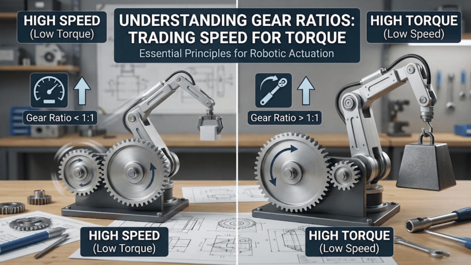
A gear ratio describes how many times the input shaft (connected to the motor) must rotate for the output shaft (connected to the load) to complete one full revolution, and it defines the fundamental trade-off in mechanical power transmission: increasing the gear ratio reduces output speed proportionally while increasing output torque by the same factor, meaning a 10:1 gear ratio makes the output shaft spin ten times slower than the motor but produces ten times more torque—allowing a small, fast motor to drive a heavy load it could never move directly. This speed-for-torque exchange is the cornerstone of virtually every mechanical drive system in robotics, from gearboxes and wheel drives to robot arm joints and winch mechanisms.
Introduction
A small electric motor spins at 10,000 RPM but produces barely enough torque to turn a pencil. Yet inside a robotic arm, a motor no bigger than your thumb lifts a payload ten times its own weight. In a motorized camera pan-tilt, a motor that would spin freely in your fingers holds a heavy camera precisely in any orientation. In a robot drivetrain, a motor rated for a fraction of a newton-meter of torque pushes a robot weighing two kilograms up a ramp. How do small motors accomplish these seemingly impossible tasks?
The answer is gears—specifically, gear ratios. Gears are mechanical transformers. Just as an electrical transformer exchanges voltage for current (or current for voltage) while conserving power, a gear train exchanges speed for torque (or torque for speed) while approximately conserving mechanical power. The laws governing this exchange are simple, elegant, and profoundly important for anyone designing or building robots.
Understanding gear ratios is not just theoretical knowledge. Every time you select a motor for a robot joint, calculate whether your drivetrain can climb a slope, decide between a high-speed and high-torque gearbox, or troubleshoot why a robot arm oscillates instead of holding steady—gear ratios are central to the analysis. This article builds that understanding completely, from the basic physics through practical calculation to real design decisions in robotics.
The Fundamental Principle: Conservation of Mechanical Power
The deepest insight behind gear ratios is that gears don’t create power—they redirect it. A gear train is a mechanical power converter, and like all practical converters, it can only output the power it receives (minus losses to friction and heat).
Mechanical power is the product of torque and angular velocity:
Power = Torque × Angular velocity
P = τ × ωIn consistent SI units (watts, newton-meters, radians per second):
- If torque is in N·m and angular velocity in rad/s, power is in watts
- 1 RPM = 2π/60 radians per second ≈ 0.1047 rad/s
Because power is conserved (ignoring efficiency losses for now):
Power_input = Power_output
τ_input × ω_input = τ_output × ω_outputRearranging:
τ_output / τ_input = ω_input / ω_output = Gear ratioThis single equation captures the entire essence of gear ratios: whatever factor you multiply the torque by, you divide the speed by the same factor, and vice versa. There is no free lunch—more torque always means proportionally less speed.
This principle holds for every type of gearing: spur gears, planetary gears, worm gears, belt drives, chain drives, and friction drives. The mechanism differs, but the fundamental speed-torque exchange is universal.
Defining Gear Ratio
The gear ratio is formally defined as the ratio of input speed to output speed:
Gear ratio = Input RPM / Output RPM
           = Output torque / Input torque (ignoring efficiency losses)
= Number of teeth on output gear / Number of teeth on input gear (for a simple gear pair)A gear ratio of 5:1 (read as “five to one”) means:
- The input shaft rotates 5 times for every 1 rotation of the output shaft
- The output shaft rotates at 1/5 the input shaft speed
- The output shaft produces 5 times the input shaft torque (ignoring friction)
A gear ratio greater than 1:1 is called a reduction (or step-down)—speed is reduced, torque is increased. This is what most robot actuators use: high-speed, low-torque motors geared down to low-speed, high-torque output for driving wheels, joints, and mechanisms.
A gear ratio less than 1:1 (for example, 1:5) is called an overdrive (or step-up)—speed is increased, torque is reduced. This is less common in robotics but appears in applications like camera focus drives where fast, low-force motion is needed.
Calculating Gear Ratio from Tooth Counts
For a meshing gear pair, the gear ratio equals the ratio of tooth counts:
Gear ratio = Teeth on driven gear / Teeth on driving gearIf the driving gear (attached to the motor) has 10 teeth and the driven gear (attached to the output) has 40 teeth:
Gear ratio = 40 / 10 = 4:1The 40-tooth gear rotates once for every 4 rotations of the 10-tooth gear. The output shaft speed is 1/4 the input speed; output torque is 4× input torque (before efficiency losses).
Gear Trains: Multiplying Ratios
Most practical gearboxes use multiple gear pairs in series (a gear train). The overall ratio of a gear train is the product of the individual stage ratios:
Overall ratio = Stage 1 ratio × Stage 2 ratio × Stage 3 ratio × ...Example: A three-stage gear train with ratios of 4:1, 5:1, and 5:1:
Overall ratio = 4 × 5 × 5 = 100:1A motor running at 10,000 RPM with this gearbox drives the output at 10,000 / 100 = 100 RPM. If the motor produces 0.05 N·m (50 mN·m) torque:
Output torque ≈ 0.05 N·m × 100 × efficiency = 4.5 N·m (at 90% efficiency)This is how small motors achieve the high torques required for robot arms, steering mechanisms, and drive systems for heavy robots. Ratios of 50:1 to 500:1 are common in robot actuators.
Types of Gear Systems in Robotics
Different gear geometries and arrangements offer different trade-offs in compactness, efficiency, load capacity, and self-locking behavior. The four types most important in robotics are spur gears, planetary gears, worm gears, and bevel gears.
Spur Gears
Spur gears are the simplest and most common gear type: cylindrical gears with straight teeth parallel to the rotation axis. Two spur gears of different sizes mesh on parallel shafts, creating a single-stage reduction.
Advantages:
- Simple and inexpensive to manufacture
- High efficiency (95–99% per stage for quality gears)
- Easy to visualize and calculate
- Available in many standard sizes, tooth counts, and modules
Disadvantages:
- Generate noise and vibration (teeth engage abruptly rather than gradually)
- Require each stage to have its own parallel shaft, making multi-stage gearboxes bulky
- Large tooth forces create significant shaft bending loads
Robotics applications: Open gear drives where compactness isn’t critical, 3D printer Z-axis drives, simple winches, custom gear trains where specific ratios are needed, and educational robot builds where cost and simplicity are paramount.
Calculating spur gear geometry:
Module (m) = Pitch diameter / Number of teeth
           = 1/Diametral pitch (imperial)

Pitch diameter = Module × Number of teeth

Center distance = (Pitch diameter 1 + Pitch diameter 2) / 2

For meshing gears: both must have the same module (or diametral pitch)

Example:
Gear 1: 12 teeth, module 1
Gear 2: 48 teeth, module 1

Pitch diameter 1 = 1 × 12 = 12 mm
Pitch diameter 2 = 1 × 48 = 48 mm
Center distance = (12 + 48) / 2 = 30 mm
Gear ratio = 48 / 12 = 4:1When designing 3D-printed spur gears for robots, module 1 or module 1.5 gears work well for small-to-medium loads. Keep tooth counts above 12 to avoid undercutting (a geometry defect that weakens the tooth root).
Planetary Gear Systems
Planetary (epicyclic) gearboxes achieve high reduction ratios in a compact, coaxial arrangement—the input and output shafts share the same axis, unlike spur gear trains where each stage introduces a parallel shaft offset.
A planetary gear system has three components:
- Sun gear: Central gear driven by the motor shaft
- Planet gears: Two to four gears that mesh with the sun gear, mounted on a rotating carrier
- Ring gear: An internal gear (teeth on the inside) that meshes with the planet gears
By holding one component fixed and driving another, different ratios are achieved:
Most common configuration (ring gear fixed):
Gear ratio = 1 + (Ring gear teeth / Sun gear teeth)

Example: Sun = 12 teeth, Ring = 36 teeth
Ratio = 1 + (36/12) = 1 + 3 = 4:1

Another configuration (carrier fixed, ring output):
Ratio = Ring teeth / Sun teeth = 36/12 = 3:1Why planetary gears dominate premium robotics actuators:
Compactness: A planetary stage achieves 3:1 to 10:1 ratio in a package barely larger than the gears themselves—far more compact than an equivalent spur gear train.
Coaxial output: Input and output share one axis, enabling clean, compact actuator designs where the motor and output shaft are inline.
Load sharing: Multiple planet gears share the load simultaneously, distributing tooth forces across two, three, or four contact points instead of one. This gives planetary gearboxes very high torque density—high torque capacity for their size and weight.
High efficiency: Multiple load-sharing paths and rolling contact geometry give planetary stages 95–98% efficiency.
Almost every high-quality robot servo, BLDC motor gearbox, and precision actuator uses planetary gearing. The Maxon, Faulhaber, and REV Robotics actuators widely used in professional robotics are planetary gearbox motors.
Worm Gears
A worm gear consists of a threaded worm (resembling a screw) meshing with a worm wheel (a helical gear). The worm is always the input (connected to the motor), and the worm wheel is the output.
The unique property: self-locking
The lead angle of most worm gears is small enough that the gear is self-locking—the output shaft cannot back-drive the input. Applied force on the output shaft cannot cause the worm to rotate, because the geometry creates a friction lock. This is unlike spur and planetary gears, where a force on the output shaft causes the input shaft to rotate (back-driving).
Self-locking is enormously valuable in certain robotics applications:
- Robot arms that need to hold a position without continuous motor current
- Lifting mechanisms (winches, elevators, scissor lifts) that must hold load without power
- Steering systems that must resist road forces without active correction
The trade-off: efficiency
The same geometry that creates self-locking causes high sliding friction between the worm and wheel teeth, giving worm gears much lower efficiency than spur or planetary gears—typically 40–70% efficiency. This means a significant portion of motor power is converted to heat rather than useful output torque.
Calculating worm gear ratio:
Gear ratio = Number of teeth on worm wheel / Number of starts on worm

"Starts" = the number of separate helical threads on the worm
Single-start worm: ratio = teeth on wheel (e.g., 40-tooth wheel → 40:1)
Double-start worm: ratio = teeth/2 (40-tooth wheel → 20:1)
Triple-start worm: ratio = teeth/3 (40-tooth wheel → 13.3:1)

Single-start worms are self-locking at most lead angles.
Multi-start worms may or may not be self-locking depending on lead angle.Robotics applications: Pan-tilt camera mounts (hold pointing direction without current), small robot arm joints (hold position), solar tracker drives, antenna aiming mechanisms, and any lifting application requiring load holding.
Bevel Gears
Bevel gears transmit rotation between intersecting shafts—most commonly at 90°. They’re used when you need to change the direction of power transmission, such as driving a wheel axle from a motor mounted perpendicular to it.
Miter gears are a subset of bevel gears with equal tooth counts on both gears (ratio = 1:1), used purely for direction change without speed or torque change.
Spiral bevel gears (curved teeth) engage more gradually than straight bevel gears, producing less vibration and noise at higher speeds—used in high-performance differentials and precision drives.
Robotics applications: Differential gearboxes (splitting drive from one motor to two wheels), right-angle drives in compact spaces, helicopter tail rotor drives, and custom mechanisms requiring directional change combined with speed reduction.
Efficiency: The Real-World Correction Factor
All the gear ratio calculations above assume 100% efficiency—that all the power from the input appears at the output. In reality, every gear mesh has friction losses that reduce output power. The efficiency of a gear stage is the ratio of output power to input power:
Efficiency (η) = Output power / Input power

Output torque = Input torque × Gear ratio × Efficiency
Output torque (real) = Input torque × Gear ratio × ηTypical efficiency values per stage:
| Gear Type | Efficiency per Stage |
|---|---|
| Spur gears (quality, lubricated) | 97–99% |
| Helical gears | 96–98% |
| Planetary gears (quality) | 95–98% |
| Bevel gears | 93–97% |
| Chain drive (lubricated) | 97–99% |
| Belt drive (V-belt) | 93–98% |
| Worm gear (self-locking range) | 40–70% |
| Worm gear (high lead angle) | 70–90% |
For multi-stage gearboxes, efficiencies multiply:
Overall efficiency = η₁ × η₂ × η₃ × ...

Three-stage planetary gearbox (each stage 97%):
Overall efficiency = 0.97 × 0.97 × 0.97 = 0.913 = 91.3%This has a direct consequence for robot battery life: a less efficient gearbox wastes more motor power as heat, draining the battery faster for the same useful output. High-efficiency gearing is particularly important for battery-powered mobile robots.
For worm gears, efficiency has an additional subtlety: the efficiency changes with load and speed. At light loads, friction losses as a fraction of output are proportionally larger, giving worse effective efficiency. At heavy loads near rated torque, efficiency approaches its rated value.
Practical Calculations: Working with Real Robot Gearboxes
Let’s work through a series of practical calculations that arise in real robotics design.
Calculation 1: Robot Drive System
Problem: You have a motor rated at 6000 RPM and 0.1 N·m torque. You want to drive 70mm diameter wheels at a maximum speed of 0.8 m/s. What gear ratio do you need?
Step 1: Find the required wheel RPM
Wheel circumference = π × 0.070 m = 0.220 m
Required wheel RPM = (0.8 m/s) / (0.220 m/rev) × 60 s/min = 218 RPMStep 2: Calculate gear ratio
Gear ratio = Motor RPM / Wheel RPM = 6000 / 218 = 27.5:1Round to a convenient available gearbox ratio: 25:1 or 30:1.
Step 3: Verify output torque
At 25:1 ratio (assume 90% efficiency):
Output torque = 0.1 N·m × 25 × 0.90 = 2.25 N·m

Wheel radius = 35 mm = 0.035 m
Drive force per wheel = 2.25 / 0.035 = 64 N

For a 2 kg robot (19.6 N weight), this is more than adequate traction.
Robot can handle significant slopes and loads.Step 4: Check speed with selected ratio
At 25:1 ratio:
Wheel RPM = 6000 / 25 = 240 RPM
Speed = 240 × 0.220 / 60 = 0.88 m/s

Slightly over target—acceptable. Use motor speed control to limit to 0.8 m/s.
Calculation 2: Robot Arm Joint
Problem: A robot arm joint must lift a 500g payload at the end of a 200mm arm link. The motor produces 50 mN·m (0.05 N·m) torque. What gear ratio is needed? What will the joint’s angular speed be?
Step 1: Calculate required joint torque
Force at tip = 0.5 kg × 9.81 m/s² = 4.9 N (payload weight)
Required torque = Force × Arm length = 4.9 N × 0.200 m = 0.98 N·m

Add margin for arm link self-weight (assume 100g arm, centered at 100mm):
Arm torque = 0.1 × 9.81 × 0.100 = 0.098 N·m
Total required torque = 0.98 + 0.098 = 1.078 N·mStep 2: Calculate required gear ratio
Gear ratio = Required output torque / (Motor torque × efficiency)
Assuming 85% gearbox efficiency:
Gear ratio = 1.078 / (0.05 × 0.85) = 25.4:1

Round up for margin: 30:1Step 3: Check joint speed
Motor speed: 1000 RPM at rated torque (typical for small brushed motor)
Joint angular speed = 1000 / 30 = 33.3 RPM
= 33.3 × 360° / 60 = 200°/second

This is quite fast for a robot arm joint—may want slower, more controlled motion.
Consider increasing ratio to 50:1 or 100:1 for more precise position control
and more torque margin at the cost of reduced speed.This is a common design trade-off: more reduction gives more torque and slower, more controllable speed. For manipulation tasks requiring precision, slower is often better.
Calculation 3: Winch for Lifting
Problem: A winch must lift a 5 kg load at 50 mm/s using a drum with 40mm radius. Motor: 12V DC, 8000 RPM free-running, 0.08 N·m stall torque. Choose an appropriate gear ratio.
Step 1: Required lifting torque
Lifting force = 5 × 9.81 = 49 N
Required drum torque = 49 × 0.040 = 1.96 N·mStep 2: Required drum RPM
Drum surface speed = 50 mm/s = 0.05 m/s
Drum circumference = 2π × 0.040 = 0.251 m
Drum RPM = 0.05 / 0.251 × 60 = 11.95 RPM ≈ 12 RPMStep 3: Calculate gear ratio
Operating motor RPM (at load, roughly half free-running): ~4000 RPM
Gear ratio = 4000 / 12 = 333:1

Verify torque (at 85% efficiency):
Output torque = 0.04 × 333 × 0.85 = 11.3 N·m

Required: 1.96 N·m — more than sufficient. Safety factor of ~5.8×.With a 333:1 ratio and a worm gear stage (for self-locking), the winch holds the load when power is removed—essential for safety in any lifting application.
Off-the-Shelf Gearboxes vs. Custom Gear Trains
In practice, robotics builders choose between using pre-manufactured gearbox motors and designing custom gear trains.
Gearbox Motors (Gearmotors)
The most common approach: purchase a motor with an integrated gearbox already attached. Gearmotors come in many configurations:
Spur gearbox motors (N20, TT motors, standard yellow hobby gearmotors): Inexpensive, widely available, built-in gear reduction. The yellow TT motor (used in countless Arduino robot kits) has a built-in spur gearbox. Ratios typically range from 30:1 to 200:1. Efficiency moderate (85–90%). These work fine for light-duty robots but have significant backlash and modest torque ratings.
Planetary gearbox motors (Pololu gearmotors, Maxon, Faulhaber): Compact, high-efficiency, low-backlash. Pololu’s micro metal gearmotors pair tiny DC motors with planetary gearboxes in ratios from 5:1 to 1000:1—an enormous selection for a small price. For quality robotics where precision matters, planetary gearmotors are the standard choice.
Servo motors: Hobby servos are complete actuators with motor, gearbox, position sensor, and control electronics integrated. The gearbox inside is typically a multi-stage spur or planetary train. Servo gearboxes range from cheap plastic (suitable for light loads only) to quality metal gearing (handles significant torques reliably).
Stepper motors with gearboxes: Combine the inherent position precision of steppers with additional torque multiplication. Common in precision positioning applications.
When to Build a Custom Gear Train
Custom gear trains are appropriate when:
- No available gearbox motor provides the exact ratio, output shaft configuration, or mounting geometry needed
- Very low cost is essential (3D-printed gears can be manufactured for cents)
- Educational purposes where understanding gear design is part of the learning objective
- Unusual arrangements needed (right-angle drive, distributed gearbox, very high torque density)
For most robotics projects, purchasing gearmotors is far more practical than designing custom gearboxes. The engineering effort, manufacturing quality, and long-term reliability of purpose-designed gearmotors typically exceeds what a custom gear train can achieve in a comparable project time.
Belt and Chain Drives: Non-Gear Alternatives
Gear trains aren’t the only way to transmit mechanical power and achieve speed reduction. Belt and chain drives offer important advantages in certain robotics applications.
Toothed (Timing) Belts
Timing belts have teeth on their inner surface that engage with matching sprocket teeth, preventing slipping. They’re used extensively in 3D printers (for linear axis motion) and robotics (for driving wheels from a remote motor location).
Advantages over gears:
- Quiet operation (no gear meshing noise)
- Can transmit power between parallel shafts at any center distance without intermediate shaft stages
- Absorb shock loads elastically (belt stretches slightly, cushioning impacts)
- Easy to adjust center distance by changing belt length
- No lubrication required for most robotics applications
Disadvantages:
- Stretch over time, requiring tension adjustment
- Can skip teeth under very high shock loads if tension isn’t adequate
- Not suitable for very high torques without very wide belts
Belt drive ratio calculation:
Ratio = Driven sprocket teeth / Driving sprocket teeth

Example: 20-tooth motor sprocket, 60-tooth output sprocket
Ratio = 60 / 20 = 3:1

Belt pitch must match sprocket pitch (GT2 2mm pitch is standard in hobby robotics)Roller Chain Drives
Roller chains (like bicycle chains) transmit power through sprocket teeth and are suited for higher-torque applications than timing belts.
Advantages: High torque capacity, very high efficiency (97–99%), durable, easily spliced to any length.
Disadvantages: Require lubrication, produce noise, heavy relative to belts, stretch over time.
Roller chains appear in larger robot drives and industrial robotics where high torque and long life are important.
Backlash: The Hidden Problem in Gear Systems
Backlash is the small amount of play between meshing gear teeth—the tiny gap between the driving tooth face and the driven tooth face. When the direction of rotation reverses, the driving teeth must travel through this gap before engaging the driven teeth again. During this gap traversal, no torque is transmitted and the output shaft position is indeterminate.
Backlash matters enormously in precision robotics:
Position error: A gearbox with 1° of backlash means the output shaft can be anywhere within a 1° window around its commanded position. For a robot arm with a 100:1 gearbox and 1° of backlash at the output, the motor-side backlash is 0.01°—measured at the motor, negligible—but the joint output position uncertainty is a full 1°.
Control instability: PID position controllers can oscillate when backlash is present. When the controller drives the joint toward the target, it overshoots slightly. The controller reverses to correct, but due to backlash, the initial reverse motion produces no output movement—the controller “sees” no response and increases its command. When the gear teeth finally engage in reverse, the joint moves with the accumulated command—another overshoot. This cycle produces persistent hunting oscillations.
Mitigation strategies:
Anti-backlash gear pairs: Two gear halves on the same shaft, spring-loaded apart. Each half meshes with opposite sides of the driven gear teeth, eliminating the gap. Complex and expensive but effective.
Preloaded gear meshes: Using an adjustable center distance to load the gears firmly together, eliminating the gap. Increases friction and wear but reduces backlash.
Approaching from one direction: In software, always approach a target position from the same direction. This keeps the gear teeth loaded against the same side, eliminating the direction-reversal backlash contribution.
Using direct drive or harmonic drives: High-end robot joints (like those in Universal Robots collaborative arms) use harmonic drive reducers—a flexible spline drive system with zero backlash. More expensive but essential for precision manipulation.
Choosing the Right Gear Ratio for Your Application
Selecting an appropriate gear ratio involves balancing several competing requirements. Here’s a systematic approach:
Step 1: Determine Required Output Parameters
What speed (RPM or rad/s) do you need at the output? What torque is required to do the work? These come from your application analysis—robot weight on a slope, arm payload and length, winch load and speed, etc.
Step 2: Know Your Motor’s Operating Point
Motors produce maximum power at approximately half their stall torque and half their free-running speed. Operating too close to stall torque causes overheating and reduced efficiency. Operating at very low load wastes motor potential. Design your gear ratio so the motor operates at 30–70% of its stall torque under normal load for best efficiency and thermal performance.
Good operating target:
Motor operating torque = 30–70% of stall torque
Motor operating RPM = 40–80% of free-running RPM

For a motor with 0.1 N·m stall torque and 6000 RPM free-running:
Target operating torque: 0.03–0.07 N·m
Target operating RPM: 2400–4800 RPM

If load requires 2 N·m output torque at 50 RPM:
Required ratio (at 85% efficiency) = 2.0 / (0.05 × 0.85) = 47:1

Motor RPM with this ratio = 50 × 47 = 2350 RPM ✓ (within target range)Step 3: Consider Speed of Response
Higher gear ratios give more torque but slower movement. For a PID-controlled joint, you want enough speed to respond within your control loop’s requirements. A robot arm joint that takes 5 seconds to move 10° can’t track fast trajectories regardless of how good the control algorithm is.
Step 4: Account for Back-Drivability Requirements
Do you need the mechanism to back-drive (allow external forces to move it when unpowered)? If yes, avoid worm gears and use spur or planetary gears. If you need the mechanism to hold its position under load without motor current, a worm gear is advantageous.
Step 5: Add Safety Margin
Always design with a torque margin of at least 1.5–2× the calculated requirement. Real loads have peaks that exceed averages, starting torque is higher than running torque, and theoretical efficiency values are never perfectly achieved in practice.
Gear Ratio Selection Quick Reference
| Application | Typical Ratio | Priority | Gear Type |
|---|---|---|---|
| Small robot wheels (100g–1kg robot) | 30:1–100:1 | Speed + traction | Spur or planetary gearmotor |
| Medium robot wheels (1kg–5kg) | 50:1–200:1 | Torque + efficiency | Planetary gearmotor |
| Robot arm joint (light payload) | 50:1–200:1 | Position precision | Planetary or harmonic |
| Robot arm joint (heavy payload) | 100:1–500:1 | High torque | Planetary or harmonic |
| Pan-tilt camera mount | 50:1–200:1 | Self-locking | Worm gear |
| Lifting winch | 100:1–500:1 | Load holding + torque | Worm or planetary |
| Conveyor belt | 20:1–100:1 | Speed + continuous duty | Spur or chain |
| Steering mechanism | 10:1–50:1 | Precision + back-drive | Planetary |
| Drone motor (direct drive) | 1:1 | Speed | No gearbox |
| 3D printer axis | 2:1–5:1 | Precision, low backlash | Belt drive |
Implementing Gear Ratio Calculations in Robot Code
Understanding gear ratios also matters at the software level. When using motor encoders for position and velocity feedback, the gear ratio is a critical conversion factor:
// Converting encoder counts to wheel rotation with gearbox

const float MOTOR_ENCODER_CPR = 64.0;    // Counts per motor revolution
const float GEAR_RATIO = 50.0;           // 50:1 gearbox
const float WHEEL_DIAMETER_MM = 70.0;    // mm

// Total counts per wheel revolution = encoder CPR × gear ratio
const float WHEEL_ENCODER_CPR = MOTOR_ENCODER_CPR * GEAR_RATIO;
// = 64 × 50 = 3200 counts per wheel revolution

// Wheel circumference in mm
const float WHEEL_CIRCUMFERENCE = PI * WHEEL_DIAMETER_MM;
// = 3.14159 × 70 = 219.9 mm

volatile long encoderCount = 0;

void encoderISR() { encoderCount++; }

float getDistanceMM() {
  // Convert encoder counts to distance traveled
  return (encoderCount / WHEEL_ENCODER_CPR) * WHEEL_CIRCUMFERENCE;
}

float getWheelRPM(long countDelta, float timeDeltaSeconds) {
  // Convert count rate to wheel RPM
  float motorRPM = (countDelta / MOTOR_ENCODER_CPR) / timeDeltaSeconds * 60.0;
  float wheelRPM = motorRPM / GEAR_RATIO;
  return wheelRPM;
}

float getMotorRPM(long countDelta, float timeDeltaSeconds) {
  // Motor RPM directly from encoder counts
  return (countDelta / MOTOR_ENCODER_CPR) / timeDeltaSeconds * 60.0;
}

void setup() {
  Serial.begin(9600);
  attachInterrupt(digitalPinToInterrupt(2), encoderISR, RISING);
}

unsigned long lastTime = 0;
long lastCount = 0;

void loop() {
  unsigned long now = millis();
  if (now - lastTime >= 100) {  // Update every 100ms
    long delta = encoderCount - lastCount;
    float dt = (now - lastTime) / 1000.0;

    float wheelRPM = getWheelRPM(delta, dt);
    float distanceMM = getDistanceMM();
    float speedMMs = wheelRPM * WHEEL_CIRCUMFERENCE / 60.0;

    Serial.print("Distance: "); Serial.print(distanceMM, 1); Serial.print(" mm | ");
    Serial.print("Wheel RPM: "); Serial.print(wheelRPM, 1); Serial.print(" | ");
    Serial.print("Speed: "); Serial.print(speedMMs, 1); Serial.println(" mm/s");

    lastCount = encoderCount;
    lastTime = now;
  }
}This code correctly accounts for the gear ratio between the motor (where the encoder is mounted) and the wheel (the actual output). A common beginner mistake is dividing encoder counts only by the encoder CPR—giving motor revolutions rather than wheel revolutions. The gear ratio must always be applied to convert from motor-shaft quantities to output-shaft quantities.
Similarly, when commanding motor speed through a PID controller, if your setpoint is in wheel RPM, multiply by the gear ratio to get the equivalent motor RPM to target:
float targetWheelRPM = 60.0;   // Desired wheel speed
float targetMotorRPM = targetWheelRPM * GEAR_RATIO;  // = 60 × 50 = 3000 RPM
// This is the setpoint for your motor speed PID controllerCommon Gear Ratio Mistakes and How to Avoid Them
Mistake 1: Ignoring efficiency Calculating output torque as simply (motor torque × gear ratio) without accounting for gearbox efficiency leads to overestimating available torque. A 100:1 worm gearbox at 60% efficiency gives only 60× torque multiplication, not 100×. Always multiply by estimated efficiency.
Mistake 2: Confusing motor torque curves Motor torque isn’t constant—it decreases from stall torque at zero RPM to zero at free-running RPM. Make sure your calculations use the torque the motor actually produces at its operating RPM, not the stall torque specification.
Mistake 3: Not accounting for encoder-to-output ratio in code As shown in the code example above: always apply the gear ratio when converting encoder measurements from motor-shaft to output-shaft quantities.
Mistake 4: Ignoring backlash in precision applications For a robot arm that needs 0.5° angular precision, a gearbox with 2° of output backlash makes the precision target unachievable regardless of encoder resolution or control algorithm quality.
Mistake 5: Selecting ratio only for torque, ignoring speed of response A very high gear ratio provides plenty of torque but may make the joint too slow for your application. Always verify that the resulting output speed is adequate for your fastest required movements.
Summary
Gear ratios are one of the most fundamental tools in robotics mechanical design. The core principle—that gears trade speed for torque or torque for speed while approximately conserving power—is simple, but its implications reach into every aspect of robot design: motor selection, wheel diameter choice, arm payload capacity, joint speed and precision, battery life, and control system stability.
The four main gear types in robotics each occupy a specific niche: spur gears for simple, affordable reductions; planetary gears for compact, high-efficiency, high-torque-density actuators; worm gears for self-locking applications requiring load holding; and bevel gears for right-angle power transmission. Belt and chain drives extend the options to remote shaft arrangements and shock-absorbing applications.
Calculating the right gear ratio follows a consistent pattern: determine required output torque and speed, know your motor’s operating characteristics, calculate the ratio that maps motor output to load requirements, verify the motor operates at a healthy point on its torque-speed curve, and add safety margin. Applying this process before purchasing motors and gearboxes saves enormous frustration compared to discovering mid-project that your system is underpowered, overpowered, too slow, or too fast.
The next article builds on this mechanical foundation to tackle robot chassis design—how the physical structure of a robot body determines not just its strength and weight, but its stability, serviceability, center of gravity, and ultimately how reliably it performs its intended task.