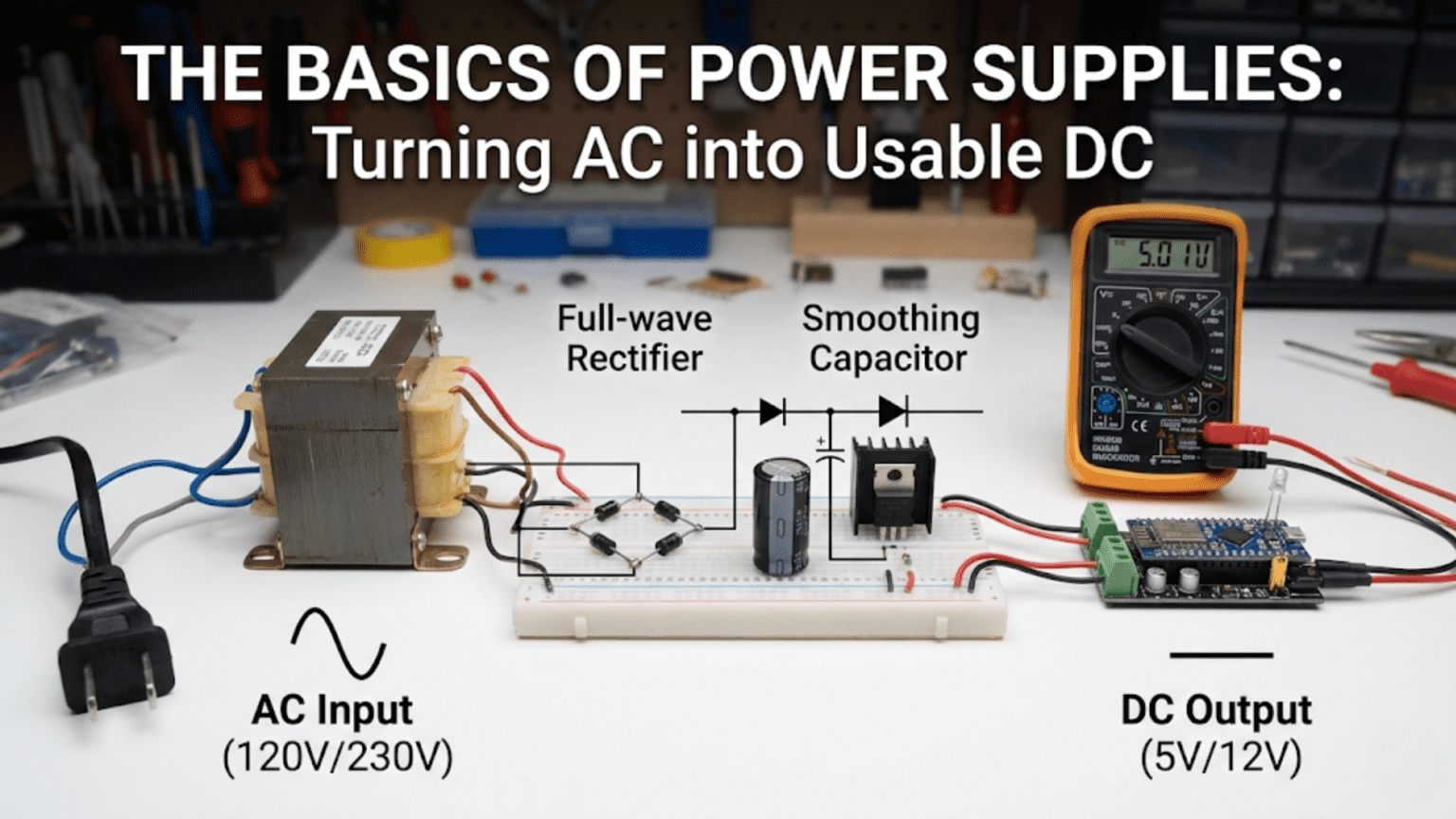
A power supply converts AC mains voltage (120V or 240V at 50/60Hz) into the stable DC voltages that electronic circuits require through four sequential stages: (1) a transformer steps the high mains voltage down to a safer, lower AC voltage; (2) a rectifier (diode bridge) converts the AC to pulsating DC by allowing current to flow in only one direction; (3) a large filter capacitor smooths the pulsating DC into relatively steady DC with small ripple; and (4) a voltage regulator removes the remaining ripple and provides precise, stable DC voltage regardless of load current or input voltage variations. This four-stage architecture—transform, rectify, filter, regulate—is the foundation of every linear DC power supply from simple wall adapters to laboratory bench supplies.
Introduction: The Universal First Stage
Every electronic device that plugs into a wall outlet—every phone charger, laptop adapter, audio amplifier, LED light, router, and appliance with a microcontroller—contains a power supply that performs the same fundamental function: converting the AC voltage from the mains into one or more stable DC voltages that the circuitry inside can use.
This conversion is not optional or interchangeable—it is the necessary interface between two incompatible electrical systems. The electrical grid delivers power as alternating current (AC) because AC can be efficiently transformed to high voltages for long-distance transmission and back down for local use. But modern electronics—microcontrollers, digital logic, LEDs, sensors, amplifiers—run on direct current (DC) at specific, stable voltages. A microcontroller needs exactly 3.3V DC. An operational amplifier might need ±15V DC. An LED driver needs 12V DC. None of these can run directly from 120V or 240V AC mains.
The power supply bridges this gap. It takes the high-voltage, alternating waveform from the wall and produces the low-voltage, constant potential that circuits require. And while modern switch-mode power supplies (the small, lightweight adapters for phones and laptops) use sophisticated high-frequency switching techniques to achieve this conversion with high efficiency in small packages, the fundamental concepts are best understood through the simpler, older technology: the linear power supply.
Linear power supplies—built from transformers, diodes, capacitors, and linear regulators—dominated electronics from the invention of the diode rectifier through the 1980s. They remain in use today for applications requiring low noise, simple design, or high reliability. More importantly, understanding the linear supply provides the conceptual foundation for understanding all power conversion: the roles of transformation, rectification, filtering, and regulation apply universally, even when implemented with different components or techniques.
This comprehensive guide builds power supply understanding from first principles through practical design. We’ll explore each of the four stages in depth, derive the design formulas from physics, work through complete design examples with real components, examine the trade-offs and practical considerations, and connect this knowledge to both classic linear designs and modern switching supplies.
Part 1: The Four Stages of AC-to-DC Conversion
Overview: Transform → Rectify → Filter → Regulate
Every linear DC power supply follows this four-stage architecture:
Stage 1 — Transformer: Steps mains voltage (120V or 240V AC) down to a lower, safer AC voltage (typically 6V–24V AC). Input: High-voltage AC Output: Low-voltage AC
Stage 2 — Rectifier: Converts AC (alternating current, bidirectional) to pulsating DC (current flows in one direction only). Input: Low-voltage AC Output: Pulsating DC (full-wave rectified)
Stage 3 — Filter Capacitor: Smooths the pulsating DC by storing charge during voltage peaks and releasing it during voltage valleys. Input: Pulsating DC with large ripple Output: Relatively steady DC with small ripple
Stage 4 — Voltage Regulator: Removes remaining ripple and provides precise, stable output voltage independent of load current and input voltage variations. Input: Unregulated DC with ripple Output: Regulated, clean DC at specified voltage
The complete signal flow:
Mains AC (120V/240V, 50/60Hz)
    ↓
[Transformer: Step-down to 12V AC]
    ↓
[Rectifier: Bridge diodes]
    ↓
Pulsating DC (~17V peak, 120Hz ripple)
    ↓
[Filter: Large electrolytic capacitor]
    ↓
Unregulated DC (15–17V with ~1V ripple)
    ↓
[Regulator: 7812 or LM317]
    ↓
Regulated DC (exactly 12V, <5mV ripple)Part 2: Stage 1 — The Transformer
Why Step Down?
Mains voltage (120V or 240V) is far too high for most electronic circuits:
- Dangerous to humans
- Difficult to insulate safely in compact equipment
- Creates unnecessarily high voltage stress on components
- Most circuits need 3.3V, 5V, 12V, or 24V — orders of magnitude lower
The transformer steps voltage down while providing galvanic isolation from the mains—no electrical connection between the dangerous mains side and the safe low-voltage secondary side.
Selecting Transformer Secondary Voltage
The transformer secondary voltage must account for voltage losses in subsequent stages:
Voltage budget: V_secondary_RMS → V_rectified_peak → V_after_filter → V_regulator_input
For regulated 12V DC output using 7812 linear regulator:
Required final output: 12V DC Regulator dropout: ~2.5V (7812 needs at least 14.5V input to maintain 12V output) Minimum regulator input: 12V + 2.5V = 14.5V DC
Allowing for ripple (let’s say 1V peak-to-peak): Required DC voltage after filter: 14.5V + 0.5V (half ripple) = 15V DC average
Rectifier diode drops: 2 × 0.7V = 1.4V (full-wave bridge) Required peak voltage at rectifier input: 15V + 1.4V = 16.4V peak
Relationship between RMS and peak for sinusoid: V_peak = V_RMS × √2 = V_RMS × 1.414 V_secondary_RMS = V_peak / 1.414 = 16.4V / 1.414 = 11.6V RMS
Choose transformer: 12V RMS secondary (closest standard value)
Actual peak voltage: 12V × 1.414 = 16.97V ≈ 17V peak
Margin verification: 17V peak – 1.4V (diodes) = 15.6V DC (before filter) With capacitor filter and modest ripple: ~15V average DC at regulator input 15V > 14.5V minimum → sufficient ✓
Transformer VA Rating
The transformer must be rated for the power it will deliver:
VA rating = V_secondary × I_secondary
For 12V secondary supplying 1A to the load: VA_minimum = 12V × 1A = 12VA
Add 20–30% margin for transformer efficiency and peak current during capacitor charging: VA_selected = 12VA × 1.3 = 15.6VA → Choose 15VA or 20VA transformer
Part 3: Stage 2 — Rectification
Half-Wave Rectification
The simplest rectifier uses one diode:
Transformer Secondary
      ~ ──[Diode]──┬── DC+
      ~            │
                  [Load]
                   │
GNDOperation:
- Positive half-cycle: Diode conducts, current flows through load
- Negative half-cycle: Diode blocks, no current flows
Output: Pulsating DC at half the input frequency (60Hz output from 60Hz AC input).
Disadvantages:
- Wastes half the AC power (only uses positive half-cycles)
- High ripple (large voltage variation)
- Poor transformer utilization
Half-wave rectification is rarely used except in the simplest, lowest-power applications.
Full-Wave Bridge Rectification
The standard rectifier uses four diodes in a bridge configuration:
Transformer Secondary
                  ~
                  │
            ┌─────┼─────┐
            │     │     │
          [D1]    │   [D2]
            │     │     │
      DC+ ──┴─────┘     └───── DC+
                  │
                [Load]
                  │
      GND ────────┼─────────── GND
                  │
            ┌─────┘     ┌─────
            │           │
          [D3]         [D4]
            │           │
            └─────┬─────┘
                  │
                  ~

D1, D2, D3, D4: 1N4007 (or equivalent rectifier diodes rated ≥ 1A, ≥ 50V)Operation:
Positive half-cycle (top terminal positive): Current flows: Top → D1 → Load → D3 → Bottom
Negative half-cycle (bottom terminal positive): Current flows: Bottom → D2 → Load → D4 → Top
Key insight: In both half-cycles, current flows through the load in the same direction (top-to-bottom in the diagram). The AC has been rectified to pulsating DC.
Output frequency: 120Hz for 60Hz AC input (both half-cycles used)
Voltage drop: Two diodes in series: V_drop ≈ 2 × 0.7V = 1.4V
Diode Selection
Voltage rating (PIV — Peak Inverse Voltage): Each diode must withstand the peak transformer voltage during the half-cycle when it’s reverse-biased. PIV_minimum = V_transformer_peak × √2 (for bridge rectifier)
For 12V RMS transformer (17V peak): PIV_minimum = 17V × 1.4 = 24V
Use diodes rated well above this: 1N4007 (1000V PIV) is extreme overkill but universally available and robust.
Current rating: Diodes must handle the peak charging current of the filter capacitor, which can be much higher than the average load current.
For 1A average load: Peak current during capacitor charging: 3–5× average = 3–5A
1N4007: 1A continuous, suitable for 1A average loads with reasonable filter capacitor For >1A loads: Use 1N5400 series (3A) or bridge rectifier module
Part 4: Stage 3 — Filtering
Why Filtering Is Necessary
After rectification, the voltage is pulsating DC:
- Rises to peak during each AC half-cycle
- Falls toward zero between peaks
- 120Hz ripple frequency (for 60Hz mains full-wave rectified)
This 120Hz variation is unacceptable for most circuits. The filter capacitor smooths it.
The Filter Capacitor
A large electrolytic capacitor connected across the rectifier output acts as an energy reservoir:
Charging phase (rectifier conducting): When the rectified voltage is above the capacitor voltage, diodes conduct. Current flows from the transformer through the diodes, splitting between the load and the capacitor. The capacitor charges to the peak voltage.
Discharging phase (rectifier not conducting): When the rectified voltage falls below the capacitor voltage, diodes reverse-bias and stop conducting. The capacitor now supplies all the load current, slowly discharging.
Result: The voltage only falls slightly during each discharge cycle before the next peak recharges it. The ripple (peak-to-peak voltage variation) is much smaller than the pulsating DC without filtering.
Filter Capacitor Value Calculation
The ripple voltage depends on:
- Load current (I_load)
- Capacitance (C)
- Ripple frequency (f_ripple = 120Hz for 60Hz mains full-wave)
Ripple formula (approximation for continuous conduction mode): V_ripple_pp = I_load / (f_ripple × C)
Where:
- V_ripple_pp = peak-to-peak ripple voltage
- I_load = load current (A)
- f_ripple = 120Hz (for 60Hz full-wave)
- C = filter capacitance (F)
Example: Load current: 1A Desired ripple: ≤ 1V peak-to-peak C_minimum = I_load / (f_ripple × V_ripple) = 1A / (120Hz × 1V) = 0.00833F = 8,333μF
Choose: 10,000μF (standard value, provides margin)
With 10,000μF: Actual ripple = 1A / (120 × 10,000×10⁻⁶) = 1A / 1.2 = 0.833V peak-to-peak ✓
Filter Capacitor Specifications
Voltage rating: Must exceed the peak rectified voltage: V_cap_rating > V_transformer_peak – V_diode_drop
For 12V RMS transformer: V_peak = 17V – 1.4V = 15.6V Choose capacitor rated ≥ 25V (standard rating with good margin)
Ripple current rating: The capacitor must handle the RMS ripple current — the AC current through the capacitor as it charges and discharges.
For our 1A load, ripple current ≈ 0.5–1A RMS (depends on conduction angle and waveform)
Standard power supply electrolytics (105°C rated) typically handle 1–2A ripple current for large values (10,000μF). Check datasheet.
Low-ESR preferred: Equivalent series resistance (ESR) of the capacitor contributes additional voltage drop and heating. Low-ESR capacitors (often labeled “low impedance” or “105°C”) provide better filtering and longer life.
Part 5: Stage 4 — Voltage Regulation
Why Regulation Is Necessary
After filtering, the DC voltage still has problems:
- Residual ripple (hundreds of millivolts)
- Voltage varies with load current (lighter load → higher voltage)
- Voltage varies with mains input voltage (110V vs. 120V mains → different transformer output)
A voltage regulator actively maintains constant output voltage regardless of these variations.
Linear Regulators: The 78xx and LM317 Families
78xx series (fixed voltage):
- 7805: +5V output
- 7809: +9V output
- 7812: +12V output
- 7815: +15V output
- 79xx: Negative voltage equivalents (-5V, -12V, etc.)
LM317 (adjustable voltage): Output voltage set by external resistors: V_out = 1.25V × (1 + R2/R1)
Dropout voltage: The minimum difference between input and output required for regulation. 7812: ~2.5V dropout (needs ≥14.5V input to regulate 12V output) LM317: ~1.5V dropout (better for low-voltage applications)
Linear Regulator Circuit
Basic 7812 regulated supply:
Unregulated DC input (15–18V) ──┬── IN [7812] OUT ──┬── +12V regulated
                                │                   │
                             [0.33μF]            [0.1μF]
                             (input)            (output)
                                │                   │
                               GND ────────────────GND

0.33μF (input capacitor): Provides local energy storage if regulator is far from filter capacitor
0.1μF (output capacitor): Improves transient response and stabilityOutput specifications:
- Voltage: 12V ±4% (typical)
- Output current: Up to 1A (with heatsink)
- Ripple rejection: 60–80dB (99.9%+ of input ripple removed)
LM317 Adjustable Regulator
For non-standard voltages:
Unregulated DC ──┬── IN [LM317] OUT ──┬── V_out
                 │            ADJ     │
              [0.1μF]          │   [0.1μF]
                 │            [R1: 240Ω]
                GND            │
                               ├── GND
                               │
[R2: Variable]V_out = 1.25V × (1 + R2/R1)
For 12V output with R1 = 240Ω: R2 = R1 × (V_out/1.25 – 1) = 240Ω × (12/1.25 – 1) = 240Ω × 8.6 = 2,064Ω → Use 2kΩ potentiometer
Heat Dissipation and Heatsinking
Linear regulators dissipate power as heat: P_dissipation = (V_in – V_out) × I_load
For 7812 with 17V input, 12V output, 1A load: P_dissipation = (17V – 12V) × 1A = 5W
This 5W must be removed through a heatsink, or the regulator will overheat and shut down (thermal protection) or fail.
Thermal resistance calculation: θ_JA = (T_J_max – T_A) / P_dissipation
T_J_max = 125°C (maximum junction temperature, from datasheet) T_A = 50°C (ambient temperature, worst case) θ_JA_required = (125 – 50) / 5W = 15°C/W
TO-220 package (7812 standard package) has θ_JA ≈ 50°C/W without heatsink — insufficient!
Heatsink required: θ_heatsink ≤ 15°C/W Use a heatsink rated for 10–15°C/W or lower; apply thermal compound between regulator and heatsink.
Part 6: Complete Design Example
Design Specification
Goal: 12V DC regulated power supply, 1A output current, from 120V AC mains.
Design decisions:
Transformer: Secondary voltage: 12V RMS (calculated earlier) VA rating: 20VA (provides margin for 12W load + losses)
Rectifier: Full-wave bridge: 4× 1N4007 diodes (or GBU bridge module)
Filter capacitor: Ripple target: 1V peak-to-peak C = I_load / (f × V_ripple) = 1A / (120Hz × 1V) = 8,333μF Selected: 10,000μF, 25V, low-ESR electrolytic
Regulator: 7812 (fixed 12V output, TO-220 package) Input capacitor: 0.33μF ceramic or film Output capacitor: 0.1μF ceramic
Heatsink: Calculated thermal resistance: ≤15°C/W Selected: Aluminum heatsink, 10°C/W rating, with thermal compound
Complete Schematic
120V AC Mains
     │
  [Fuse: 0.5A slow-blow]
     │
  [ON/OFF Switch]
     │
Primary ┌─────────┐
   ~ ───┤         │
   ~ ───┤ 12V 20VA│
        │Transform│
        └─────────┘
             ~ Secondary (12V AC)
             │
        Bridge Rectifier
         [4× 1N4007]
             │
        ────┬──── +DC (~17V pulsating)
            │
    [C1: 10,000μF, 25V] (filter)
            │
        ────┴──── GND
            │
    [0.33μF ceramic] (regulator input bypass)
            │
        IN [7812] OUT ──┬── +12V regulated, 1A max
           [GND]        │
            │       [0.1μF ceramic]
           GND           │
GNDPerformance Predictions
Output voltage: 12V ±4% (11.5V–12.5V) Output current capability: 1A continuous (with heatsink) Ripple voltage: <10mV (regulator removes >99% of 0.8V input ripple) Efficiency: ~60–70% (typical for linear regulator) Total power consumption from mains: ~20W (12W to load + ~8W heat in regulator and transformer losses)
Part 7: Modern Switch-Mode Power Supplies (SMPS)
Why Switching Supplies Dominate
The linear supply we’ve designed works well but has significant disadvantages:
- Large and heavy: Transformer is bulky (50/60Hz requires large iron core)
- Low efficiency: ~60–70% (significant heat in regulator)
- Fixed input voltage: Designed for 120V or 240V — not universal
Modern switch-mode power supplies (SMPS) overcome these limitations:
- High frequency: Switching at 50kHz–1MHz enables tiny transformers and inductors
- High efficiency: 85–95% (less heat, smaller or no heatsink)
- Wide input range: 85–265V AC automatically accommodates worldwide mains voltages
- Compact and lightweight: Phone chargers, laptop adapters are SMPS
SMPS Operating Principle
Instead of linearly dropping voltage (and dissipating power as heat), an SMPS:
- Rectifies mains AC to high-voltage DC (~170V from 120V mains)
- Switches this DC on and off rapidly (50kHz–1MHz) through a transformer
- High-frequency transformer steps voltage down efficiently
- Output is rectified and filtered
- Feedback controls switching duty cycle to regulate output voltage
Key advantage: Switching losses (during transition) + conduction losses (when fully on) << linear regulator losses
Comparison Table: Linear vs. Switching Power Supplies
| Characteristic | Linear Supply | Switch-Mode Supply |
|---|---|---|
| Technology | Transformer + rectifier + filter + linear regulator | High-frequency switching converter |
| Efficiency | 50%–70% | 80%–95% |
| Size / Weight | Large (heavy transformer) | Compact (small high-frequency transformer) |
| Heat Dissipation | Significant (regulator losses) | Low (high efficiency) |
| Output Noise | Very low (<5 mV ripple) | Higher (50–200 mV switching noise) |
| Electromagnetic Interference (EMI) | Minimal | Can be significant (requires filtering) |
| Complexity | Simple (few components) | Complex (ICs, feedback, protection circuits) |
| Cost | Low for low power | Moderate to high |
| Input Voltage Range | Fixed (120V or 240V) | Wide (85–265V universal input) |
| Transient Response | Moderate | Fast (high bandwidth feedback loop) |
| Isolation | Excellent (low-frequency transformer) | Good (high-frequency transformer) |
| Best For | Audio systems, precision analog circuits, low-noise applications | Portable devices, high-power systems, efficiency-critical applications |
Troubleshooting Power Supply Problems
No Output Voltage
Check:
- Mains power reaching transformer (measure primary voltage)
- Transformer secondary voltage (should be rated AC voltage)
- Rectifier diodes (test with multimeter diode check; one or more may be shorted or open)
- Filter capacitor (may be open/failed; measure voltage across it)
- Regulator (may be in thermal shutdown or damaged; check input voltage, output voltage, and heat)
Output Voltage Too Low
Possible causes:
- Excessive load current (check actual load current vs. rated maximum)
- Regulator dropout (input voltage insufficient; increase transformer voltage or reduce output voltage)
- Damaged regulator or diodes
Excessive Ripple
Possible causes:
- Filter capacitor failed (dried out, ESR increased) → Replace
- Filter capacitor too small for load current → Increase capacitance
- Regulator not functioning (input ripple appearing at output) → Check regulator input voltage
Regulator Overheating
Causes:
- Excessive power dissipation: (V_in – V_out) × I_load too high
- Insufficient heatsinking
Solutions:
- Reduce input voltage (use lower transformer secondary voltage)
- Reduce load current
- Add or improve heatsink
Transformer Overheating/Humming
Causes:
- Overloaded (load current exceeds transformer VA rating)
- Shorted turns (internal fault)
- DC current through primary (rare; usually due to circuit fault)
Solution:
- Verify load current ≤ transformer rating
- Replace transformer if faulty
Conclusion: The Foundation of Practical Electronics
The power supply is the first stage of every mains-powered electronic device and arguably the most critical — everything downstream depends on it providing clean, stable DC voltage. Understanding how it works — the cascade of transformation, rectification, filtering, and regulation — builds the foundation for understanding all power electronics.
Core Principles Reviewed
Four stages transform AC to regulated DC. Each stage has a specific function: the transformer steps voltage down and provides isolation; the rectifier converts AC to pulsating DC; the filter capacitor smooths the pulsations; and the regulator provides precise, stable output voltage.
Component selection follows physics. Transformer voltage is determined by required output plus all downstream losses. Filter capacitor size follows directly from ripple requirements and load current. Regulator heatsink requirements follow from power dissipation calculations. Each choice is calculable, not arbitrary.
Linear supplies trade efficiency for simplicity. They waste power as heat but provide the cleanest possible DC output with minimal complexity — still preferred for precision analog, audio, and low-noise applications.
Switching supplies dominate modern designs. Their high efficiency and compact size make them universal in portable electronics and high-power applications, despite higher complexity and noise.
From Wall Outlet to Circuit
Every microcontroller you program, every LED you light, every sensor you interface with needs a power supply that converts 120V or 240V AC into the specific DC voltage that circuit requires. Whether it’s a simple 7805 regulator in a hobby project or a sophisticated multi-output SMPS in a desktop computer, the fundamental challenge remains the same: bridging the gap between the AC grid and the DC circuits that define modern electronics.
Understanding this bridge — the physics, the design formulas, the component selections, the trade-offs — is understanding the invisible infrastructure that makes all of electronics possible. The power supply may be the least glamorous circuit in any system, but it is the one upon which all others depend.