Encoders are sensors attached to rotating shafts—typically motor axles or wheels—that convert physical rotation into countable electrical pulses, allowing robots to measure exactly how far they have traveled, how fast they are moving, and in what direction, with each pulse representing a precise fraction of one full rotation. Without encoders, robots can only guess their position based on how long motors have been running; with encoders, robots achieve accurate dead reckoning navigation, precise speed control, and reliable position tracking regardless of surface variations or motor inconsistencies.
You command your robot to drive exactly one meter forward and stop precisely at a target position. Without feedback, you estimate: “My motors run at roughly 0.3 m/s, so I’ll run them for about 3.3 seconds.” But surface friction varies, battery voltage drops as the session progresses, carpet slows the robot more than tile, and the two motors never spin at quite the same speed. Your “exactly one meter” command actually produces anywhere from 0.7 to 1.4 meters of travel depending on conditions. The robot has no idea where it actually ended up.
Now equip the same robot with wheel encoders. Each tiny rotation of the wheel generates a precisely countable pulse. Travel 1000 pulses and you’ve moved exactly the distance those 1000 pulses represent—regardless of surface, battery state, or motor variation. Need to travel exactly one meter? Count pulses until you reach the equivalent distance, then stop. Need to maintain 0.5 m/s? Count how many pulses arrive per second and adjust motor power to keep that rate constant. Need the left and right wheels to travel equal distances through a turn? Count pulses on both sides and stop when they match.
Encoders transform robots from open-loop guessers into closed-loop machines with genuine knowledge of their motion. This article explains how encoders work physically and electrically, how to connect them to microcontrollers, how to write reliable interrupt-driven code to count pulses accurately, and how to use encoder data for the two most fundamental applications in mobile robotics: precise distance control and accurate speed regulation. By the end, you’ll understand why professional robots universally use encoders and how to bring this capability to your own projects.
How Encoders Convert Rotation to Pulses
Understanding the physical mechanism behind encoders helps you select the right type, troubleshoot problems, and appreciate the precision they provide.
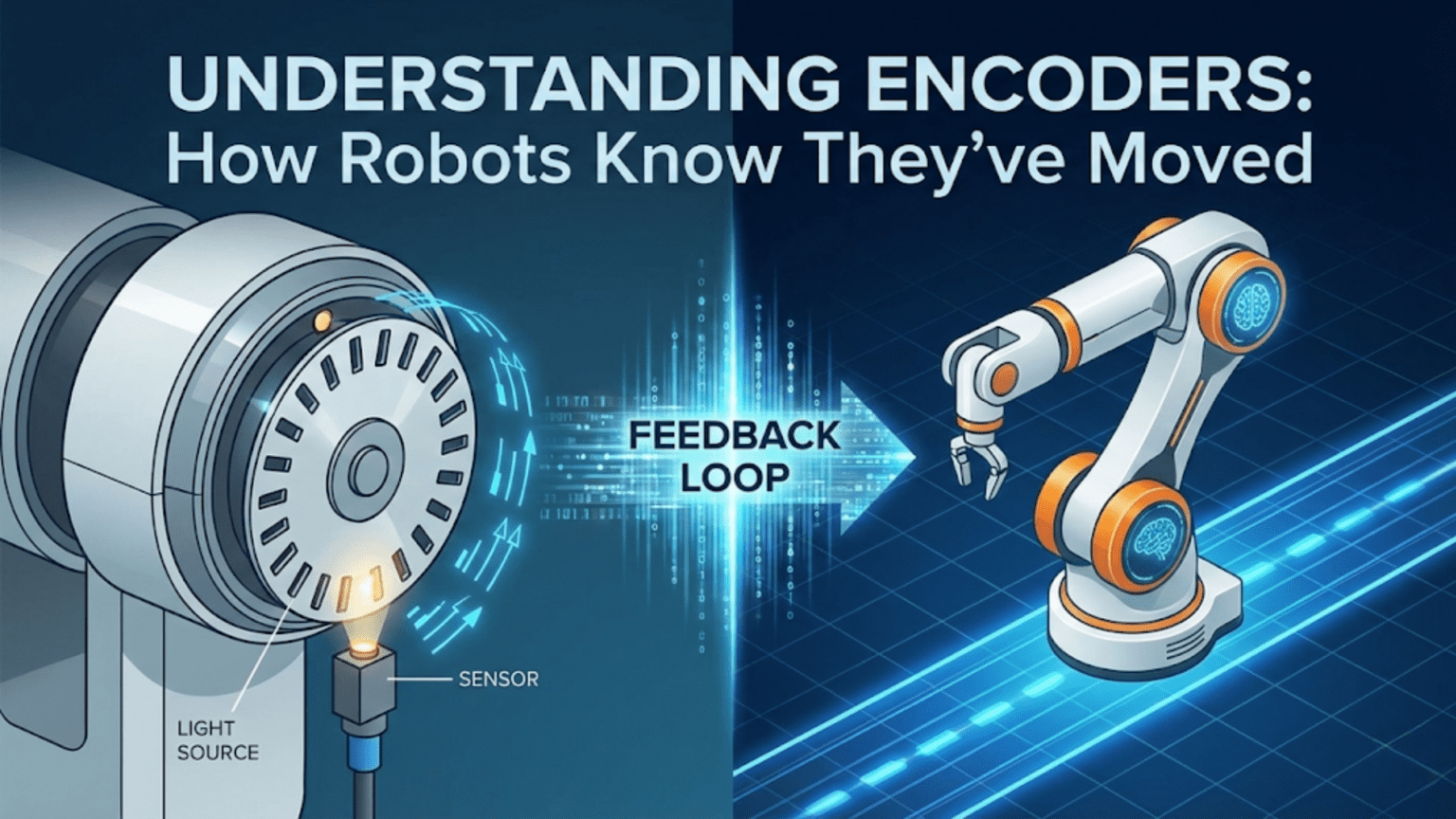
Incremental Optical Encoders
The most common type for robotics uses a disk with evenly spaced slots or reflective strips attached to the rotating shaft. A light source (LED) shines through the slots while a photodetector on the other side detects when light passes and when it’s blocked.
As the shaft rotates, slots pass between the LED and detector in sequence. Each slot creates one complete light-dark-light transition, generating one electrical pulse. Count these pulses and you know how many slots have passed—which translates directly to shaft rotation.
Resolution determines accuracy. A disk with 20 slots per revolution generates 20 pulses per revolution (PPR). A disk with 360 slots generates 360 PPR—one pulse per degree of rotation. Higher resolution means more precise position measurement but requires faster counting (more pulses per unit time at the same speed).
The math connecting pulses to distance: If your encoder has 360 PPR and your wheel has a 6 cm radius (12 cm diameter):
- Wheel circumference = π × diameter = 3.14159 × 12 cm ≈ 37.7 cm
- Distance per pulse = 37.7 cm ÷ 360 pulses ≈ 0.105 cm per pulse
- For 1 meter (100 cm) of travel: 100 cm ÷ 0.105 cm/pulse ≈ 952 pulses
So counting 952 pulses means you’ve traveled almost exactly one meter.
Quadrature Encoders: Adding Direction Detection
Simple encoders with one output channel can count pulses but can’t determine direction—both forward and reverse rotation produce identical pulse patterns. Quadrature encoders solve this with two output channels (typically called Channel A and Channel B) positioned 90 degrees out of phase.
How quadrature works: When rotating forward, Channel A leads Channel B—A goes HIGH, then B goes HIGH, then A goes LOW, then B goes LOW, in a repeating cycle. When rotating backward, the sequence reverses: B leads A. By checking which channel transitions first, your code determines rotation direction.
State sequence for forward rotation:
Time:      1    2    3    4    5    6    7    8
Channel A: H    H    L    L    H    H    L    L
Channel B: L H H L L H H LState sequence for backward rotation:
Time:      1    2    3    4    5    6    7    8
Channel A: H    L    L    H    H    L    L    H
Channel B: L L H H L L H HThe critical observation: When Channel A rises (LOW→HIGH), if Channel B is LOW, the motor rotates forward. If Channel B is HIGH, the motor rotates backward.
X4 Decoding: Quadrupling Resolution
By counting transitions on both channels (rising and falling edges of both A and B), you achieve four times the physical slot count—called X4 decoding. A 100 PPR encoder becomes effectively 400 counts per revolution with X4 decoding.
Standard quadrature transitions per revolution:
- X1 decoding: Count only rising edges of Channel A = 1× PPR
- X2 decoding: Count rising and falling edges of Channel A = 2× PPR
- X4 decoding: Count all edges of both channels = 4× PPR
Most Arduino implementations use X2 or X4 decoding via interrupts to maximize resolution from affordable encoders.
Magnetic Encoders
Instead of optical disks, magnetic encoders use a small permanent magnet attached to the shaft and a Hall effect sensor chip that detects the rotating magnetic field. As the magnet spins, the alternating north and south poles create alternating electrical pulses in the Hall sensor.
Advantages over optical:
- Immune to dust, dirt, and condensation that fog optical disks
- No alignment required between LED and detector
- Works in complete darkness
- Smaller and more robust physically
- Many motor gearboxes include built-in magnetic encoders
Disadvantages:
- Slightly lower resolution than high-quality optical encoders
- Magnet alignment critical for consistent readings
- Susceptible to external magnetic fields (motors, electromagnets)
Many popular hobby robot motors—particularly N20 gear motors and similar units—come with integrated magnetic encoders, making them popular choices for precision robotics projects.
Mechanical Encoders
The simplest and cheapest encoders use mechanical contacts that open and close as the shaft rotates. These work for very slow rotations but suffer from contact bounce (the contacts physically bounce, creating spurious pulses) that degrades accuracy at higher speeds.
For robotics, avoid mechanical encoders for wheel position tracking. They work adequately for manual dials and user controls but prove unreliable for motor shaft applications.
Choosing the Right Encoder for Your Robot
Several factors determine which encoder suits your specific application.
Resolution Requirements
For general navigation (driving to approximate positions):
- 20-100 PPR: Adequate for basic distance tracking
- Accuracy: ±1-5 cm over 1 meter travel
For precise positioning (accurate stopping, tight turns):
- 100-360 PPR: Good for careful navigation
- Accuracy: ±1-5 mm over 1 meter travel
For high-precision tasks (pick and place, repetitive positioning):
- 360-1000+ PPR: Necessary for sub-millimeter accuracy
- Consider X4 decoding to multiply effective resolution
Speed Range Compatibility
Higher speeds require encoders that can generate and count pulses fast enough. At 1000 RPM with a 360 PPR encoder:
- Pulses per second = 1000 RPM × 360 PPR ÷ 60 s/min = 6,000 pulses/second
Your microcontroller must count 6,000 pulses per second reliably—well within Arduino’s interrupt capability (typically handles 100,000+ pulses/second).
At higher speeds or resolutions, consider:
- Dedicated encoder counter ICs
- Higher-performance microcontrollers
- Hardware quadrature decoders
Physical Integration
For motors with integrated encoders, matching is simple—the encoder is already mechanically coupled. For motors without built-in encoders, you must attach an encoder disk to the shaft, requiring:
- Shaft access (some motors don’t provide a rear shaft)
- Disk mounting hardware
- Optical or magnetic sensor mounting bracket
- Careful alignment
Many robot chassis kits now include motors with pre-installed encoders, significantly simplifying implementation.
Wiring Encoders to Arduino
Proper wiring ensures reliable pulse detection without missing counts or generating false pulses.
Single-Channel Encoder Wiring
For direction-agnostic counting:
Encoder          Arduino
VCC      →       5V (or 3.3V for 3.3V encoders)
GND      →       GND
OUT → Digital Pin 2 (interrupt-capable)Only pins 2 and 3 support hardware interrupts on Arduino Uno. Use these pins for encoder signals to avoid missing pulses.
Quadrature Encoder Wiring (Two Motors)
For a two-wheel drive robot with direction sensing:
Left Motor Encoder        Arduino
VCC          →            5V
GND          →            GND
Channel A    →            Pin 2 (interrupt)
Channel B    →            Pin 4 (digital read)

Right Motor Encoder       Arduino
VCC          →            5V
GND          →            GND
Channel A    →            Pin 3 (interrupt)
Channel B → Pin 5 (digital read)Why only one interrupt per encoder? Using interrupts on Channel A and reading Channel B as a regular digital input is the standard approach for Arduino Uno (which has only two interrupt pins). When Channel A changes state (interrupt triggered), read Channel B to determine direction.
Pull-up Resistors
Many encoders have open-collector outputs that require pull-up resistors. Without pull-ups, the signal floats at undefined voltage between pulses:
// Enable internal pull-ups for encoder pins
pinMode(encoderAPin, INPUT_PULLUP);
pinMode(encoderBPin, INPUT_PULLUP);If the encoder has push-pull outputs (drives HIGH and LOW), internal pull-ups are unnecessary but harmless.
Noise Filtering
High-speed motors generate significant electrical noise that can corrupt encoder signals. Add 100nF ceramic capacitors between each encoder output and ground, as close to the encoder connector as possible:
Encoder Output → [100nF capacitor] → GNDThis filters high-frequency noise without affecting encoder pulse timing.
Writing Encoder Code: Interrupt-Driven Counting
The key to reliable encoder counting is using hardware interrupts rather than polling in the main loop. When your main loop is busy with other calculations, it might miss pulses. Interrupts trigger immediately when the encoder pin changes state, regardless of what the main loop is doing.
Basic Single-Encoder Counter
// Encoder pin definitions
const int encoderAPin = 2;  // Interrupt pin
const int encoderBPin = 4;  // Direction pin

// Encoder count (use volatile for interrupt-modified variables)
volatile long encoderCount = 0;

void setup() {
  pinMode(encoderAPin, INPUT_PULLUP);
  pinMode(encoderBPin, INPUT_PULLUP);

  // Attach interrupt to Channel A - triggers on any change
  attachInterrupt(digitalPinToInterrupt(encoderAPin),
                  encoderISR, CHANGE);

  Serial.begin(9600);
}

void loop() {
  // Safe way to read volatile variable
  long count;
  noInterrupts();     // Disable interrupts briefly
  count = encoderCount;
  interrupts();       // Re-enable interrupts

  Serial.print("Encoder count: ");
  Serial.println(count);

  delay(200);
}

// Interrupt Service Routine - called on every edge of Channel A
void encoderISR() {
  // Read Channel A and B current states
  bool A = digitalRead(encoderAPin);
  bool B = digitalRead(encoderBPin);

  // Determine direction based on which channel leads
  if (A == B) {
    encoderCount++;   // Forward rotation
  } else {
    encoderCount--;   // Backward rotation
  }
}Why volatile? Variables modified inside interrupt service routines must be declared volatile. This tells the compiler not to optimize the variable into a CPU register—always read it from memory, because it can change unexpectedly at any time.
Why noInterrupts()/interrupts()? On Arduino, long variables (32-bit) are not read atomically—the processor reads them in two 16-bit chunks. An interrupt could modify the variable between the two reads, corrupting the value. Briefly disabling interrupts ensures the full 32-bit value is read consistently.
Dual-Encoder Counter for Differential Drive Robot
// Left encoder
const int leftEncoderA = 2;
const int leftEncoderB = 4;
volatile long leftCount = 0;

// Right encoder
const int rightEncoderA = 3;
const int rightEncoderB = 5;
volatile long rightCount = 0;

// Robot parameters
const float wheelDiameter = 6.5;  // cm
const float wheelBase = 15.0;     // cm (distance between wheels)
const int pulsesPerRevolution = 740;  // PPR (after gearbox)

// Calculated parameters
const float wheelCircumference = PI * wheelDiameter;  // cm
const float distancePerPulse = wheelCircumference / pulsesPerRevolution;  // cm/pulse

void setup() {
  pinMode(leftEncoderA, INPUT_PULLUP);
  pinMode(leftEncoderB, INPUT_PULLUP);
  pinMode(rightEncoderA, INPUT_PULLUP);
  pinMode(rightEncoderB, INPUT_PULLUP);

  attachInterrupt(digitalPinToInterrupt(leftEncoderA), leftISR, CHANGE);
  attachInterrupt(digitalPinToInterrupt(rightEncoderA), rightISR, CHANGE);

  Serial.begin(9600);
  Serial.println("Dual encoder initialized");
}

void loop() {
  // Safely read encoder counts
  long leftC, rightC;
  noInterrupts();
  leftC = leftCount;
  rightC = rightCount;
  interrupts();

  // Calculate distances
  float leftDist = leftC * distancePerPulse;
  float rightDist = rightC * distancePerPulse;
  float avgDist = (leftDist + rightDist) / 2.0;

  Serial.print("Left: ");
  Serial.print(leftDist, 2);
  Serial.print(" cm, Right: ");
  Serial.print(rightDist, 2);
  Serial.print(" cm, Average: ");
  Serial.print(avgDist, 2);
  Serial.println(" cm");

  delay(500);
}

void leftISR() {
  bool A = digitalRead(leftEncoderA);
  bool B = digitalRead(leftEncoderB);
  if (A == B) leftCount++;
  else leftCount--;
}

void rightISR() {
  bool A = digitalRead(rightEncoderA);
  bool B = digitalRead(rightEncoderB);
  if (A == B) rightCount++;
  else rightCount--;
}High-Performance X4 Quadrature Decoding
For maximum resolution using both edges of both channels:
// Quadrature state machine - X4 decoding
// Requires two interrupt pins per encoder (Arduino Mega or similar)

const int encA = 2;
const int encB = 3;
volatile long position = 0;
volatile int lastEncoded = 0;

void setup() {
  pinMode(encA, INPUT_PULLUP);
  pinMode(encB, INPUT_PULLUP);

  // Attach interrupts to BOTH channels for X4 decoding
  attachInterrupt(digitalPinToInterrupt(encA), updateEncoder, CHANGE);
  attachInterrupt(digitalPinToInterrupt(encB), updateEncoder, CHANGE);

  // Initialize lastEncoded with current state
  lastEncoded = (digitalRead(encA) << 1) | digitalRead(encB);

  Serial.begin(9600);
}

void loop() {
  long pos;
  noInterrupts();
  pos = position;
  interrupts();

  Serial.println(pos);
  delay(100);
}

void updateEncoder() {
  int MSB = digitalRead(encA);  // Most significant bit
  int LSB = digitalRead(encB);  // Least significant bit

  int encoded = (MSB << 1) | LSB;  // Combine into 2-bit state
  int sum = (lastEncoded << 2) | encoded;  // 4-bit transition code

  // Decode transition table
  if (sum == 0b1101 || sum == 0b0100 ||
      sum == 0b0010 || sum == 0b1011) position++;
  if (sum == 0b1110 || sum == 0b0111 ||
      sum == 0b0001 || sum == 0b1000) position--;

  lastEncoded = encoded;
}This state machine approach correctly handles all valid transitions and ignores invalid ones (which would be caused by noise), making it more robust than simple A-leads-B detection.
Practical Applications: Using Encoder Data
Raw pulse counts become powerful when you convert them into useful robot behaviors.
Application 1: Driving a Precise Distance
Command your robot to travel exactly a specified distance:
void driveDistance(float targetDistance_cm, int speed) {
  // Calculate required pulse count
  long targetPulses = (long)(targetDistance_cm / distancePerPulse);

  // Reset encoder counts
  noInterrupts();
  leftCount = 0;
  rightCount = 0;
  interrupts();

  Serial.print("Driving ");
  Serial.print(targetDistance_cm);
  Serial.print(" cm (");
  Serial.print(targetPulses);
  Serial.println(" pulses)");

  // Start motors
  setMotors(speed, speed);

  // Wait until target distance reached
  while (true) {
    long leftC, rightC;
    noInterrupts();
    leftC = leftCount;
    rightC = rightCount;
    interrupts();

    // Use average of both wheels
    long avgPulses = (abs(leftC) + abs(rightC)) / 2;

    if (avgPulses >= targetPulses) {
      break;  // Target reached
    }

    // Optional: Straightness correction
    long leftRightDiff = leftC - rightC;
    int correction = leftRightDiff * 2;  // Small correction factor
    setMotors(speed - correction, speed + correction);

    delay(5);
  }

  // Stop motors
  setMotors(0, 0);
  Serial.println("Target distance reached!");
}

void setMotors(int left, int right) {
  left = constrain(left, -255, 255);
  right = constrain(right, -255, 255);
  // Apply to your motor driver (implementation depends on hardware)
}Key feature: The straightness correction compares left and right encoder counts and adjusts motor speeds to keep both wheels traveling equal distances—automatically compensating for motor differences and surface friction variations.
Application 2: Precise Speed Control (PID)
Maintain exact wheel speed regardless of load or battery voltage:
// Speed control parameters
float targetSpeedLeft = 20.0;   // cm/s
float targetSpeedRight = 20.0;  // cm/s

// PID gains
float Kp = 8.0;
float Ki = 0.5;
float Kd = 0.2;

// PID state
float integralLeft = 0, integralRight = 0;
float lastErrorLeft = 0, lastErrorRight = 0;

// Speed measurement
volatile long leftCount = 0, rightCount = 0;
long lastLeftCount = 0, lastRightCount = 0;
unsigned long lastSpeedTime = 0;

float currentSpeedLeft = 0, currentSpeedRight = 0;

void updateSpeed() {
  unsigned long currentTime = millis();
  float deltaTime = (currentTime - lastSpeedTime) / 1000.0;  // seconds

  if (deltaTime < 0.05) return;  // Update at most 20 times/second

  // Read encoder counts safely
  long leftC, rightC;
  noInterrupts();
  leftC = leftCount;
  rightC = rightCount;
  interrupts();

  // Calculate pulse change
  long leftDelta = leftC - lastLeftCount;
  long rightDelta = rightC - lastRightCount;

  // Calculate actual speed in cm/s
  currentSpeedLeft = (leftDelta * distancePerPulse) / deltaTime;
  currentSpeedRight = (rightDelta * distancePerPulse) / deltaTime;

  // Store for next iteration
  lastLeftCount = leftC;
  lastRightCount = rightC;
  lastSpeedTime = currentTime;
}

void speedControlLoop() {
  updateSpeed();

  // Left wheel PID
  float errorLeft = targetSpeedLeft - currentSpeedLeft;
  integralLeft += errorLeft;
  integralLeft = constrain(integralLeft, -500, 500);  // Anti-windup
  float derivLeft = errorLeft - lastErrorLeft;
  float outputLeft = (Kp * errorLeft) + (Ki * integralLeft) + (Kd * derivLeft);
  lastErrorLeft = errorLeft;

  // Right wheel PID
  float errorRight = targetSpeedRight - currentSpeedRight;
  integralRight += errorRight;
  integralRight = constrain(integralRight, -500, 500);
  float derivRight = errorRight - lastErrorRight;
  float outputRight = (Kp * errorRight) + (Ki * integralRight) + (Kd * derivRight);
  lastErrorRight = errorRight;

  // Apply to motors (accumulate with base PWM or use as absolute PWM)
  static int pwmLeft = 128, pwmRight = 128;
  pwmLeft = constrain(pwmLeft + (int)outputLeft, 0, 255);
  pwmRight = constrain(pwmRight + (int)outputRight, 0, 255);

  setMotors(pwmLeft, pwmRight);

  // Debug output
  Serial.print("Speeds: L=");
  Serial.print(currentSpeedLeft, 1);
  Serial.print(" R=");
  Serial.print(currentSpeedRight, 1);
  Serial.print(" cm/s, PWM: L=");
  Serial.print(pwmLeft);
  Serial.print(" R=");
  Serial.println(pwmRight);
}

void loop() {
  speedControlLoop();
  delay(50);
}Application 3: Turning Precise Angles
Execute exact angle turns using wheel arc length calculations:
void turnAngle(float degrees, int speed) {
  // Calculate arc length each wheel must travel
  // For turning in place: arc = radius × angle (in radians)
  // Radius for in-place turn = wheelBase / 2

  float radians = degrees * PI / 180.0;
  float arcLength = (wheelBase / 2.0) * radians;  // cm

  long targetPulses = (long)(arcLength / distancePerPulse);

  Serial.print("Turning ");
  Serial.print(degrees);
  Serial.print(" degrees (");
  Serial.print(targetPulses);
  Serial.println(" pulses each wheel)");

  // Reset encoders
  noInterrupts();
  leftCount = 0;
  rightCount = 0;
  interrupts();

  // Turn: left wheel forward, right wheel backward (for left turn)
  // Adjust sign for right/left turn based on degrees sign
  int leftMotorSpeed = (degrees > 0) ? speed : -speed;   // Left: CW for right turn
  int rightMotorSpeed = (degrees > 0) ? -speed : speed;  // Right: CCW for right turn

  setMotors(leftMotorSpeed, rightMotorSpeed);

  // Wait for both wheels to reach target arc
  while (true) {
    long leftC, rightC;
    noInterrupts();
    leftC = leftCount;
    rightC = rightCount;
    interrupts();

    // Check if both wheels have traveled required arc
    if (abs(leftC) >= targetPulses && abs(rightC) >= targetPulses) {
      break;
    }

    delay(5);
  }

  setMotors(0, 0);
  Serial.println("Turn complete!");
}Application 4: Odometry — Tracking Robot Position
Calculate the robot’s X, Y position and heading angle continuously:
// Robot pose (position and orientation)
float robotX = 0;     // cm
float robotY = 0;     // cm
float robotTheta = 0; // radians (0 = pointing right)

long lastLeftOdometry = 0;
long lastRightOdometry = 0;

void updateOdometry() {
  // Read current encoder counts
  long leftC, rightC;
  noInterrupts();
  leftC = leftCount;
  rightC = rightCount;
  interrupts();

  // Calculate distance each wheel traveled since last update
  float leftDist = (leftC - lastLeftOdometry) * distancePerPulse;
  float rightDist = (rightC - lastRightOdometry) * distancePerPulse;

  // Update stored values
  lastLeftOdometry = leftC;
  lastRightOdometry = rightC;

  // Calculate robot motion
  float distTraveled = (leftDist + rightDist) / 2.0;   // Average distance
  float deltaTheta = (rightDist - leftDist) / wheelBase; // Change in heading

  // Update heading
  robotTheta += deltaTheta;

  // Keep theta within -PI to PI
  while (robotTheta > PI) robotTheta -= 2 * PI;
  while (robotTheta < -PI) robotTheta += 2 * PI;

  // Update position using midpoint heading approximation
  float midTheta = robotTheta - deltaTheta / 2.0;
  robotX += distTraveled * cos(midTheta);
  robotY += distTraveled * sin(midTheta);
}

void printPose() {
  Serial.print("X: ");
  Serial.print(robotX, 1);
  Serial.print(" cm, Y: ");
  Serial.print(robotY, 1);
  Serial.print(" cm, Heading: ");
  Serial.print(robotTheta * 180.0 / PI, 1);
  Serial.println(" degrees");
}

void loop() {
  updateOdometry();
  printPose();
  delay(100);
}What odometry enables:
- Navigate to specific coordinates
- Return to starting position
- Create simple environment maps
- Track path taken during exploration
Odometry accumulates error over time due to wheel slip, measurement uncertainty, and surface variations. For short distances (up to several meters), accuracy is good. For longer distances, periodic correction using landmarks, GPS, or other absolute positioning is necessary.
Encoder-Based Motor Control Architecture
For reliable robot navigation, structure your code in distinct layers:
// Layer 1: Low-level encoder counting (interrupt-driven)
volatile long leftPulses = 0;
volatile long rightPulses = 0;

void leftEncoderISR() { /* counts pulses with direction */ }
void rightEncoderISR() { /* counts pulses with direction */ }

// Layer 2: Speed measurement (called periodically)
float leftSpeed_cms = 0;  // cm/s
float rightSpeed_cms = 0;

void measureSpeed() {
  static long lastLeft = 0, lastRight = 0;
  static unsigned long lastTime = 0;

  unsigned long now = millis();
  float dt = (now - lastTime) / 1000.0;
  if (dt < 0.05) return;

  noInterrupts();
  long lc = leftPulses;
  long rc = rightPulses;
  interrupts();

  leftSpeed_cms = ((lc - lastLeft) * distancePerPulse) / dt;
  rightSpeed_cms = ((rc - lastRight) * distancePerPulse) / dt;

  lastLeft = lc;
  lastRight = rc;
  lastTime = now;
}

// Layer 3: Speed controller (adjusts PWM to achieve target speed)
float targetLeft_cms = 0;
float targetRight_cms = 0;
int pwmLeft = 0, pwmRight = 0;

void speedController() {
  // PID for each wheel (as shown in previous example)
}

// Layer 4: Position/navigation commands
void setTargetSpeed(float left, float right) {
  targetLeft_cms = left;
  targetRight_cms = right;
}

void driveDistance(float distance) {
  // High-level command
  float speed = 20.0;  // cm/s
  setTargetSpeed(speed, speed);
  // Monitor progress and stop when complete
}

// Main loop calls all layers in order
void loop() {
  measureSpeed();      // Layer 2
  speedController();   // Layer 3
  // Navigation logic here uses Layer 4
  updateOdometry();    // Position tracking
  delay(10);
}This layered architecture keeps code organized, separates concerns cleanly, and makes debugging easier—you can test each layer independently before integrating.
Comparison Table: Encoder Types for Robotics
| Encoder Type | Resolution | Direction Detection | Environmental Tolerance | Cost | Typical Use |
|---|---|---|---|---|---|
| Single-channel optical | Low-High (20-1000 PPR) | No | Moderate (dust affects) | $2-10 | Speed sensing, simple positioning |
| Quadrature optical | Medium-High (100-2000 PPR) | Yes | Moderate (dust affects) | $5-20 | Precision navigation, speed control |
| Integrated magnetic | Medium (100-500 PPR) | Yes | Excellent (weather-proof) | $0 (built-in) | Hobby motors, compact robots |
| Standalone magnetic | Medium-High (256-4096 PPR) | Yes | Excellent | $5-20 | Industrial, outdoor robots |
| Mechanical | Low (1-50 PPR) | No | Poor (bounce) | $0.50-2 | Manual controls only |
| Absolute encoder | High (360-65536 PPR) | Absolute position | Excellent | $30-200+ | Robot arms, precision positioning |
Common Problems and Solutions
Problem: Pulse Count Drifting or Inaccurate
Symptoms: Robot travels wrong distance; count doesn’t match expected.
Causes:
- Electrical noise generating false pulses
- Missed pulses due to polling instead of interrupts
- Incorrect PPR specification
- Wheel slipping on surface
Solutions:
// Add noise filtering capacitors (hardware)
// Use interrupts (not polling)

// Verify PPR by counting pulses for one full wheel rotation manually:
void measureActualPPR() {
  noInterrupts();
  leftCount = 0;
  interrupts();

  Serial.println("Rotate wheel EXACTLY one full turn, then press button");
  while (digitalRead(buttonPin) == HIGH) delay(10);

  noInterrupts();
  long count = leftCount;
  interrupts();

  Serial.print("Measured PPR: ");
  Serial.println(count);
}Problem: Robot Drifts During Straight-Line Travel
Symptoms: Robot curves left or right despite equal speed commands.
Causes:
- Left and right wheels have slightly different PPR
- Motor characteristics differ between left and right
- Wheel diameters not perfectly equal
Solutions:
// Measure actual ratio between wheels
float wheelRatioCorrection = 1.0;  // Adjust this based on testing

void calibrateWheelRatio() {
  // Drive straight for 1 meter, measure drift
  // If robot drifts left, increase left motor speed
  // Measure actual pulse counts for equal distance

  noInterrupts();
  leftCount = 0;
  rightCount = 0;
  interrupts();

  // Drive forward at fixed speed for fixed time
  setMotors(150, 150);
  delay(3000);
  setMotors(0, 0);

  noInterrupts();
  long lc = leftCount;
  long rc = rightCount;
  interrupts();

  wheelRatioCorrection = (float)lc / rc;

  Serial.print("Wheel ratio: ");
  Serial.println(wheelRatioCorrection, 4);
}Problem: Speed Measurement Unstable or Noisy
Symptoms: Reported speed oscillates wildly; speed control hunts.
Causes:
- Measurement interval too short (few pulses per interval)
- Encoder resolution too low for speed calculation at slow speeds
- Interrupts being missed due to processing load
Solutions:
// Use longer measurement intervals at slow speeds
const int minInterval_ms = 100;  // At least 100ms between measurements

// Apply low-pass filter to speed measurements
float filteredSpeed = 0;
const float alpha = 0.3;  // Smoothing factor

void measureSpeed() {
  // ... (measure as before) ...

  float rawSpeed = /* calculated speed */;
  filteredSpeed = (alpha * rawSpeed) + ((1 - alpha) * filteredSpeed);
}Problem: Lost Encoder Signal During Motor Operation
Symptoms: Count stops changing during motor operation; works when motor off.
Causes:
- Motor electrical noise overwhelming encoder signal
- Shared power supply causing voltage fluctuations
- Poor ground connections
Solutions:
- Add 100nF bypass capacitors on encoder power pins
- Use separate power supply for logic and motors
- Add ferrite bead on motor power leads
- Twist encoder signal wires together for noise rejection
- Add shielded cable for encoder signals
Conclusion: Encoders as the Foundation of Robot Self-Awareness
Encoders give robots something profound: genuine knowledge of their own motion. Without encoders, your robot is effectively blind to how it has actually moved—it can only hope that commands produced the intended results. With encoders, your robot knows precisely how far each wheel has turned, can calculate actual travel speed independent of motor power, can detect and correct deviations from intended paths, and can build an increasingly detailed picture of its position in the world.
This self-awareness through motion sensing is the foundation upon which all sophisticated robot navigation is built. Dead reckoning navigation, speed-regulated driving, straight-line correction, precise turning, odometry-based mapping—all rely fundamentally on accurate encoder feedback. The Mars rovers use encoders. Industrial automation systems use encoders. Self-driving vehicles use encoders. The principle scales from your hobby robot to the most sophisticated autonomous systems in the world.
The skills developed in this article—understanding encoder physics, implementing interrupt-driven counting, converting pulses to distance and speed, implementing speed control PID, and calculating odometry—form a complete toolkit for precise robot motion. These skills build directly on each other: pulse counting enables speed measurement, speed measurement enables PID control, PID control enables consistent behavior, and consistent behavior enables reliable odometry.
Start with the basics: connect one encoder, count pulses, verify the count matches physical rotation. Add direction detection with a quadrature encoder. Implement speed measurement and verify accuracy. Build speed control PID and tune it for smooth, responsive behavior. Add odometry and watch your robot track its position. Each step builds on the last, progressively expanding your robot’s self-knowledge and navigational capability.
Encoders transform the fundamental limitation of open-loop control—the inability to verify that commands produced intended results—into the central strength of closed-loop feedback: the ability to measure reality, detect deviations, and correct continuously. Master encoders, and you master the essential sensing technology that elevates robots from blind command-followers into genuinely aware, self-regulating machines.