Infrared sensors in robotics detect invisible infrared light—electromagnetic radiation just beyond the red end of the visible spectrum with wavelengths between 700 nanometers and 1 millimeter—to enable proximity detection, line following, object counting, and remote control reception without physical contact. Because infrared light behaves similarly to visible light (reflecting off surfaces, traveling in straight lines) but remains invisible to humans, IR sensors give robots a unique perceptual capability that operates reliably in both bright and dim conditions for many short-range detection tasks.
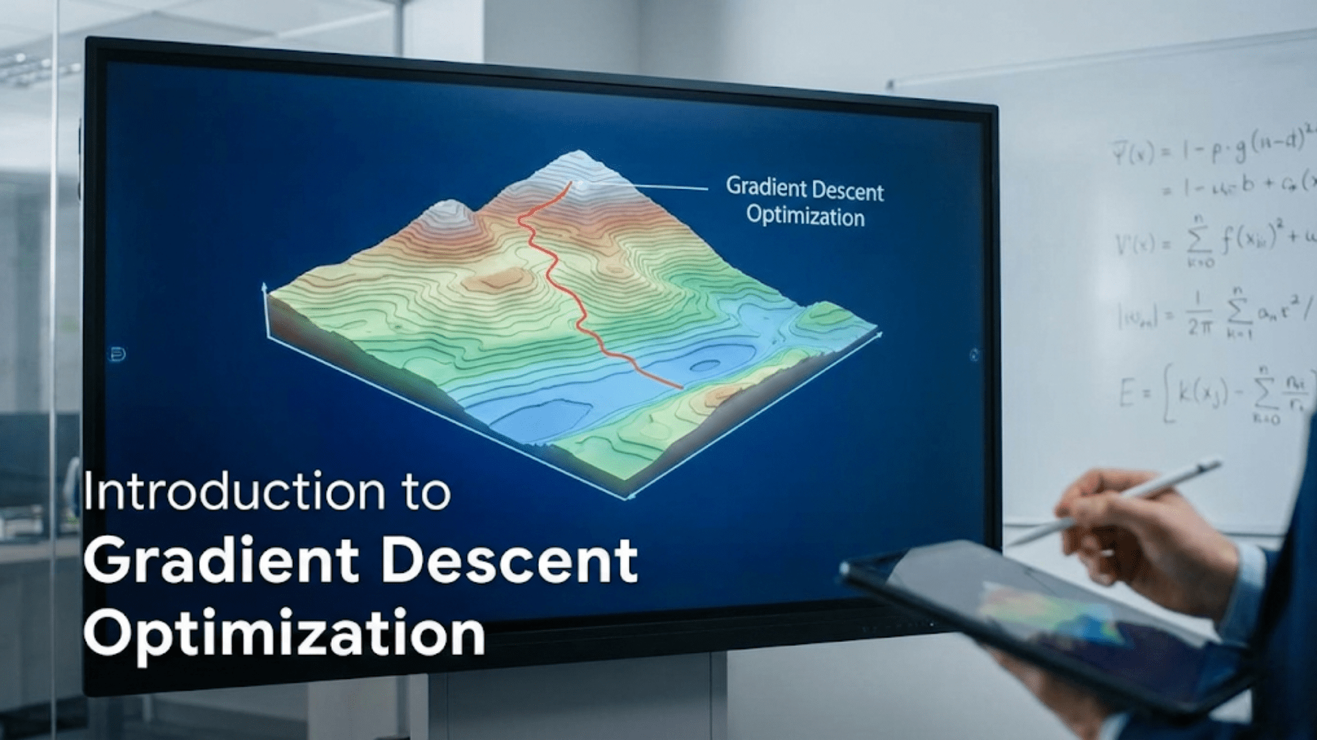
You watch your line-following robot confidently trace a black track on white paper, smoothly cornering and adjusting its path without any visible sensors that could “see” the line. Or your obstacle-avoiding robot detects objects in complete darkness, responding to invisible threats that no camera could capture under those conditions. A robot sorts colored objects by reflection intensity, counts items on a conveyor belt, or responds to remote control signals from across the room—all using sensors detecting light that human eyes cannot perceive.
Infrared sensors provide robots with a perceptual capability that exists at the boundary between the familiar and the invisible. Because infrared light follows the same physical laws as visible light—reflecting off surfaces, traveling in straight lines, varying in intensity with distance—robots equipped with IR sensors can detect surfaces, measure proximity, and recognize patterns in ways analogous to vision but simpler and more affordable. Yet because this light is invisible to humans, IR-equipped robots seem almost magical, responding to stimuli that appear to be nothing at all.
Understanding infrared sensors equips you to design more capable robots, select appropriate sensor types for specific tasks, interpret sensor data correctly, and troubleshoot the inevitable problems that arise. From the ubiquitous line-following sensor pair to sophisticated distance-measuring analog sensors and the long-range IR receivers used in remote control systems, infrared technology permeates amateur and professional robotics alike. This article provides comprehensive coverage of all major infrared sensor types, their operating principles, practical implementation, and real-world robotics applications.
The Physics of Infrared Light
Understanding infrared light’s nature helps you predict sensor behavior and design effective robotic systems.
What Is Infrared Radiation?
Infrared (IR) radiation is electromagnetic energy—the same fundamental phenomenon as visible light, radio waves, and X-rays, just at different frequencies. The electromagnetic spectrum spans an enormous range of frequencies; infrared occupies the region between visible light (400-700 nm wavelength) and microwave radiation (1 mm-1 m wavelength).
For robotics, two infrared sub-ranges matter most:
Near-Infrared (NIR): 700 nm – 1400 nm
- Closest to visible red light
- Used in proximity sensors, line followers, remote controls
- Reflected and absorbed similarly to visible light
- Silicon photodetectors respond well to these wavelengths
Thermal Infrared: 8000 nm – 14000 nm
- Emitted by objects based on their temperature
- Used in heat cameras, motion detectors (PIR sensors)
- All objects at room temperature emit thermal IR
- Different detectors required (pyroelectric, microbolometer)
Most robotics IR sensors operate in the near-infrared range (typically 850-950 nm), close enough to visible light that the physics and behavior feel intuitive.
How Infrared Reflects off Surfaces
Near-infrared light reflects off surfaces according to the same principles as visible light:
Reflectivity depends on surface color and material:
- White surfaces: High reflectivity (~80-90% of incident IR reflected)
- Black surfaces: Low reflectivity (~5-10% of incident IR absorbed and scattered)
- Shiny metal: Very high reflectivity (mirror-like, direction-dependent)
- Rough matte surfaces: Diffuse reflection (spreads in multiple directions)
This reflectivity difference is fundamental to line-following sensors: white paper reflects IR strongly back to a detector above it, while black tape or printed black ink absorbs most IR, returning little to the detector. The contrast between high and low reflectivity makes line detection reliable and straightforward.
Angle dependence: For smooth surfaces, reflection angle equals incidence angle (like a mirror). For rough surfaces, reflection spreads diffusely in multiple directions. Most robotics applications benefit from diffuse reflection, ensuring the sensor receives reflected light even if not perfectly positioned.
The Inverse Square Law
IR intensity decreases with the square of distance from the source:
Intensity = Power / (4π × distance²)
Double the distance from an IR emitter, and intensity drops to one-quarter. This inverse square relationship explains why IR proximity sensors have limited range—signal strength falls rapidly with distance, eventually dropping below detectable levels.
For a typical IR LED at 1 cm: intensity = 100% At 2 cm: intensity = 25% At 4 cm: intensity = 6.25% At 10 cm: intensity = 1%
This rapid falloff means most simple IR proximity sensors reliably detect objects only within 2-30 cm depending on emitter power, detector sensitivity, and surface reflectivity.
Types of Infrared Sensors in Robotics
Several distinct IR sensor categories serve different robotics applications. Understanding each type’s characteristics helps you select the right sensor for your specific needs.
Type 1: Digital IR Proximity Sensors
How they work: These sensors combine an IR LED emitter and photodetector in one package with built-in circuitry. When the emitted IR reflects off a nearby object and returns to the detector, an onboard comparator circuit outputs a digital HIGH or LOW signal indicating presence or absence of a nearby object.
Key characteristics:
- Output: Digital (HIGH or LOW only)
- No distance measurement capability
- Adjustable sensitivity (usually via potentiometer)
- Typical detection range: 2-30 cm
- Very simple to interface (like a button)
Common module: FC-51 The FC-51 (and similar modules) includes:
- IR LED transmitter
- IR photodetector receiver
- Comparator circuit with adjustable threshold
- Power LED (indicates power)
- Detection LED (indicates when object detected)
- Three or four pins: VCC, GND, OUT (and sometimes EN)
Wiring FC-51 to Arduino:
FC-51         Arduino
VCC    →      5V
GND    →      GND
OUT → Digital Pin 2Basic usage code:
const int irSensorPin = 2;

void setup() {
  pinMode(irSensorPin, INPUT);
  Serial.begin(9600);
}

void loop() {
  int sensorState = digitalRead(irSensorPin);

  // Note: Many IR modules output LOW when detecting (active low)
  if (sensorState == LOW) {
    Serial.println("Object detected!");
  } else {
    Serial.println("No object");
  }

  delay(100);
}Adjusting sensitivity: The onboard potentiometer adjusts the detection threshold. Turn clockwise to increase sensitivity (detect farther objects); counterclockwise to decrease sensitivity (only detect very close objects). Adjust while monitoring the detection LED for the desired response.
Best applications:
- Simple obstacle detection
- Object counting on conveyor belts
- End-stop detection for robot arms
- Line following (basic)
Type 2: Analog IR Distance Sensors (Sharp GP2Y Series)
How they work: Sharp distance sensors use triangulation rather than intensity measurement. They project an IR beam and measure the angle at which the reflected beam returns using a Position Sensitive Device (PSD). Because the beam angle varies predictably with distance, they can calculate actual distance values and output them as analog voltage.
Why triangulation beats intensity: Simple intensity measurement (strong signal = close, weak signal = far) varies with surface color and reflectivity—a white object at 30 cm might return as much signal as a black object at 5 cm. Triangulation measures beam angle regardless of intensity, providing much more consistent distance readings across different surface types.
Common models and ranges:
- GP2Y0A21YK0F: 10-80 cm range (most popular for robotics)
- GP2Y0A02YK0F: 20-150 cm range (longer range)
- GP2Y0A41SK0F: 4-30 cm range (shorter range)
- GP2Y0A710K0F: 100-550 cm range (long range)
Wiring Sharp sensor to Arduino:
Sharp Sensor    Arduino
VCC      →      5V
GND      →      GND
Vout → A0 (analog input)Reading Sharp sensor data:
const int sharpPin = A0;

void loop() {
  int rawValue = analogRead(sharpPin);

  // Convert to voltage
  float voltage = rawValue * (5.0 / 1023.0);

  // Convert voltage to distance (GP2Y0A21YK0F formula)
  // This formula is empirically derived - varies by model
  float distance_cm = 27.86 * pow(voltage, -1.15);

  // Clamp to valid range
  if (distance_cm < 10) distance_cm = 10;
  if (distance_cm > 80) distance_cm = 80;

  Serial.print("Distance: ");
  Serial.print(distance_cm);
  Serial.println(" cm");

  delay(100);
}Important notes about Sharp sensors:
- Output is nonlinear—voltage doesn’t scale linearly with distance
- Objects closer than minimum range may read as maximum range (watch for this!)
- Require filtering/averaging for stable readings
- Sensitive to ambient infrared (bright sunlight can cause issues)
Better approach using lookup table:
// Lookup table for GP2Y0A21YK0F (voltage to distance in cm)
// More accurate than formula for specific sensor
const int tableSize = 13;
const float voltages[tableSize] = {
  3.0, 2.5, 2.0, 1.7, 1.4, 1.2, 1.0, 0.88, 0.78, 0.68, 0.60, 0.55, 0.50
};
const float distances[tableSize] = {
  10, 12, 15, 18, 22, 27, 33, 40, 48, 57, 67, 75, 80
};

float getDistanceLookup(float voltage) {
  // Check bounds
  if (voltage >= voltages[0]) return distances[0];
  if (voltage <= voltages[tableSize-1]) return distances[tableSize-1];

  // Find surrounding values and interpolate
  for (int i = 0; i < tableSize - 1; i++) {
    if (voltage <= voltages[i] && voltage > voltages[i+1]) {
      float fraction = (voltage - voltages[i]) / (voltages[i+1] - voltages[i]);
      return distances[i] + fraction * (distances[i+1] - distances[i]);
    }
  }
  return -1;  // Should never reach here
}

void loop() {
  int raw = analogRead(sharpPin);
  float voltage = raw * (5.0 / 1023.0);
  float distance = getDistanceLookup(voltage);

  Serial.print("Distance: ");
  Serial.print(distance);
  Serial.println(" cm");
  delay(100);
}Type 3: IR Line Sensing Arrays
How they work: Line sensors typically use multiple IR emitter-detector pairs arranged in a row. Each pair illuminates the surface below and measures reflected intensity. White surfaces return high intensity (high analog value or digital HIGH); black surfaces return low intensity (low value or digital LOW). The pattern of which sensors see white versus black determines the line’s position relative to the robot.
Common configurations:
- 2-sensor arrays: Simple left/right detection
- 5-sensor arrays: Position calculation, curved lines
- 8-sensor arrays: High precision, complex track detection
Popular module: TCRT5000-based sensors The TCRT5000 combines an IR LED and phototransistor in a reflective sensor package optimized for surface sensing at 2-5 mm distance.
Wiring 5-sensor array:
// Five analog sensor pins
const int sensorPins[5] = {A0, A1, A2, A3, A4};
int sensorValues[5];

void readSensors() {
  for (int i = 0; i < 5; i++) {
    sensorValues[i] = analogRead(sensorPins[i]);
  }
}

void printSensorValues() {
  Serial.print("Sensors: ");
  for (int i = 0; i < 5; i++) {
    Serial.print(sensorValues[i]);
    Serial.print(" ");
  }
  Serial.println();
}Calibration for line sensors: Line sensors need calibration because surface reflectivity varies. Calibrate by exposing each sensor to both black and white surfaces:
int sensorMin[5];  // Minimum values (over black)
int sensorMax[5];  // Maximum values (over white)

void calibrateSensors() {
  Serial.println("Calibrating... Move robot over line for 3 seconds");

  // Initialize min/max arrays
  for (int i = 0; i < 5; i++) {
    sensorMin[i] = 1023;
    sensorMax[i] = 0;
  }

  // Collect samples for 3 seconds
  unsigned long startTime = millis();
  while (millis() - startTime < 3000) {
    for (int i = 0; i < 5; i++) {
      int val = analogRead(sensorPins[i]);
      if (val < sensorMin[i]) sensorMin[i] = val;
      if (val > sensorMax[i]) sensorMax[i] = val;
    }
    delay(10);
  }

  Serial.println("Calibration complete!");
  for (int i = 0; i < 5; i++) {
    Serial.print("Sensor ");
    Serial.print(i);
    Serial.print(": min=");
    Serial.print(sensorMin[i]);
    Serial.print(" max=");
    Serial.println(sensorMax[i]);
  }
}

// Get normalized reading (0 = white, 1000 = black)
int getNormalizedReading(int sensorIndex) {
  int raw = analogRead(sensorPins[sensorIndex]);
  return map(raw, sensorMin[sensorIndex], sensorMax[sensorIndex], 0, 1000);
}Calculating line position:
// Returns weighted position: 0 = far left, 2000 = far right, -1 = no line
float calculateLinePosition() {
  int weights[5] = {0, 500, 1000, 1500, 2000};  // Position values for each sensor

  long weightedSum = 0;
  long sum = 0;

  for (int i = 0; i < 5; i++) {
    int value = getNormalizedReading(i);
    weightedSum += (long)value * weights[i];
    sum += value;
  }

  if (sum < 200) return -1;  // No line detected

  return (float)weightedSum / sum;  // Weighted average position
}Type 4: IR Remote Control Receivers
How they work: TV remote controls and similar devices transmit IR pulses in specific patterns encoding button presses. The standard protocol (NEC, Sony, RC5, etc.) modulates a 38 kHz carrier signal with the data signal. IR receiver modules are specially designed to detect this 38 kHz modulated signal while filtering out other IR sources (ambient light, other sensors).
TSOP4838 and similar receivers: These three-pin modules contain a photodetector, amplifier, bandpass filter (tuned to 38 kHz), and demodulator, outputting decoded digital signals representing the remote’s transmitted codes.
Using IR Remote with Arduino:
#include <IRremote.h>  // Install via Arduino Library Manager

const int irReceiverPin = 11;
IRrecv irReceiver(irReceiverPin);
decode_results results;

void setup() {
  irReceiver.enableIRIn();  // Start IR receiver
  Serial.begin(9600);
  Serial.println("IR Remote Receiver Ready");
}

void loop() {
  if (irReceiver.decode(&results)) {
    Serial.print("Received IR code: ");
    Serial.println(results.value, HEX);

    // Map button codes to robot actions
    switch (results.value) {
      case 0xFF629D:  // Example: up arrow
        moveForward();
        Serial.println("Moving Forward");
        break;
      case 0xFFA857:  // Example: down arrow
        moveBackward();
        Serial.println("Moving Backward");
        break;
      case 0xFF22DD:  // Example: left arrow
        turnLeft();
        Serial.println("Turning Left");
        break;
      case 0xFFC23D:  // Example: right arrow
        turnRight();
        Serial.println("Turning Right");
        break;
      case 0xFF02FD:  // Example: OK button
        stopRobot();
        Serial.println("Stopped");
        break;
    }

    irReceiver.resume();  // Ready for next signal
  }
}

void moveForward() { /* motor control code */ }
void moveBackward() { /* motor control code */ }
void turnLeft() { /* motor control code */ }
void turnRight() { /* motor control code */ }
void stopRobot() { /* motor control code */ }Finding button codes: Run a code-detection sketch to discover codes from your specific remote:
void loop() {
  if (irReceiver.decode(&results)) {
    if (results.value != 0xFFFFFFFF) {  // Ignore repeat codes
      Serial.print("Button code: 0x");
      Serial.println(results.value, HEX);
    }
    irReceiver.resume();
  }
}Press each button while running this sketch; record the displayed codes for use in your control program.
Complete Line-Following Robot Implementation
Let’s build a complete line-following robot using IR sensors, demonstrating how all the pieces fit together:
// Pin definitions
const int sensorPins[5] = {A0, A1, A2, A3, A4};
const int motorLeftFwd = 3;
const int motorLeftBwd = 4;
const int motorRightFwd = 5;
const int motorRightBwd = 6;
const int motorLeftPWM = 9;
const int motorRightPWM = 10;
const int startButton = 2;

// Calibration storage
int sensorMin[5];
int sensorMax[5];

// PID control parameters
float Kp = 0.4;
float Ki = 0.0001;
float Kd = 1.5;

float lastError = 0;
float integral = 0;
const int baseSpeed = 150;

void setup() {
  // Motor pins
  pinMode(motorLeftFwd, OUTPUT);
  pinMode(motorLeftBwd, OUTPUT);
  pinMode(motorRightFwd, OUTPUT);
  pinMode(motorRightBwd, OUTPUT);

  // Button
  pinMode(startButton, INPUT_PULLUP);

  Serial.begin(9600);

  // Wait for button press to calibrate
  Serial.println("Press button to calibrate sensors");
  while (digitalRead(startButton) == HIGH) { delay(10); }
  delay(200);

  // Calibrate
  calibrateSensors();

  // Wait for button press to start
  Serial.println("Press button again to start");
  while (digitalRead(startButton) == HIGH) { delay(10); }
  delay(500);
  Serial.println("Running!");
}

void loop() {
  // Get line position (0-2000, 1000 = center)
  float linePos = calculateLinePosition();

  if (linePos < 0) {
    // Line lost - stop
    setMotors(0, 0);
    Serial.println("Line lost!");
    return;
  }

  // Calculate error (-1000 to +1000, 0 = centered)
  float error = 1000 - linePos;

  // PID calculation
  integral += error;
  float derivative = error - lastError;
  float correction = (Kp * error) + (Ki * integral) + (Kd * derivative);
  lastError = error;

  // Apply correction to motor speeds
  int leftSpeed = baseSpeed - correction;
  int rightSpeed = baseSpeed + correction;

  leftSpeed = constrain(leftSpeed, -255, 255);
  rightSpeed = constrain(rightSpeed, -255, 255);

  setMotors(leftSpeed, rightSpeed);
}

void setMotors(int leftSpeed, int rightSpeed) {
  // Left motor
  if (leftSpeed >= 0) {
    digitalWrite(motorLeftFwd, HIGH);
    digitalWrite(motorLeftBwd, LOW);
    analogWrite(motorLeftPWM, leftSpeed);
  } else {
    digitalWrite(motorLeftFwd, LOW);
    digitalWrite(motorLeftBwd, HIGH);
    analogWrite(motorLeftPWM, -leftSpeed);
  }

  // Right motor
  if (rightSpeed >= 0) {
    digitalWrite(motorRightFwd, HIGH);
    digitalWrite(motorRightBwd, LOW);
    analogWrite(motorRightPWM, rightSpeed);
  } else {
    digitalWrite(motorRightFwd, LOW);
    digitalWrite(motorRightBwd, HIGH);
    analogWrite(motorRightPWM, -rightSpeed);
  }
}

void calibrateSensors() {
  Serial.println("Calibrating - slowly move robot over black line...");

  for (int i = 0; i < 5; i++) {
    sensorMin[i] = 1023;
    sensorMax[i] = 0;
  }

  // Spin in place slowly during calibration to cover both surfaces
  setMotors(100, -100);

  unsigned long startTime = millis();
  while (millis() - startTime < 3000) {
    for (int i = 0; i < 5; i++) {
      int val = analogRead(sensorPins[i]);
      if (val < sensorMin[i]) sensorMin[i] = val;
      if (val > sensorMax[i]) sensorMax[i] = val;
    }
  }

  setMotors(0, 0);
  Serial.println("Calibration complete!");
}

float calculateLinePosition() {
  int weights[5] = {0, 500, 1000, 1500, 2000};
  long weightedSum = 0;
  long sum = 0;

  for (int i = 0; i < 5; i++) {
    int raw = analogRead(sensorPins[i]);
    int normalized = map(raw, sensorMin[i], sensorMax[i], 0, 1000);
    normalized = constrain(normalized, 0, 1000);
    weightedSum += (long)normalized * weights[i];
    sum += normalized;
  }

  if (sum < 200) return -1;
  return (float)weightedSum / sum;
}Environmental Factors Affecting IR Sensor Performance
Understanding when IR sensors perform well—and when they struggle—prevents frustrating debugging sessions.
Ambient Infrared Interference
Sunlight: Contains substantial infrared, potentially overwhelming sensors. Outdoor robots face this challenge acutely—bright sunlight can saturate IR detectors, causing false readings or complete sensor blindness.
Solutions:
- Use sensors with optical bandpass filters tuned to LED wavelength
- Choose modulated IR sensors (38 kHz receivers filter continuous IR)
- Shield sensors from direct sunlight with physical barriers
- Use higher-powered IR LEDs to overpower ambient IR
- Test indoors first; add ambient compensation for outdoor use
Fluorescent lights: Some older fluorescent lights flicker at 50-120 Hz, producing IR pulses that can interfere with sensors.
Other IR sensors: Multiple robots or sensors in the same space may interfere with each other.
Surface Properties and Limitations
Transparent surfaces: IR passes through clear glass and some plastics—the sensor “sees” whatever is behind the transparent material.
Specular (mirror-like) reflectors: Metal, some plastics, and glossy surfaces reflect IR at specific angles. If the sensor isn’t positioned to receive the specular reflection, it may not detect these surfaces despite their high reflectivity.
Complex textures: Carpeting, fabric, and rough surfaces scatter IR unpredictably, causing variable readings.
Color temperature sensitivity: IR sensors are most sensitive to near-infrared wavelengths (850-950 nm). Some “black” materials (particularly certain plastics) reflect NIR even while absorbing visible light—what appears black to human eyes might appear bright to an IR sensor.
Practical test: Test your IR sensors with actual materials from your robot’s operating environment. Never assume sensor behavior based on visible color alone.
Operating Height and Angle
Line sensors work best at specific heights above the surface (typically 2-10 mm for TCRT5000-based sensors). Too high: signal too weak, poor contrast. Too low: sensor physically contacts surface, potential damage.
Mounting angle matters significantly for proximity sensors:
- Direct downward mounting: Measures distance below
- Angled mounting: Can see surfaces at an angle, increasing effective range
- Side mounting: Detects objects to the side
The included angle between emitter and detector determines the sensor’s effective range and angular sensitivity.
Advanced Applications
Beyond basic line following and proximity detection, IR sensors enable sophisticated robotics capabilities.
Object Counting
Count items passing a fixed point:
const int sensorPin = 2;  // Digital IR sensor
int count = 0;
int lastState = HIGH;

void loop() {
  int currentState = digitalRead(sensorPin);

  // Detect transition from not-blocked to blocked (object passing)
  if (currentState == LOW && lastState == HIGH) {
    count++;
    Serial.print("Object count: ");
    Serial.println(count);
  }

  lastState = currentState;
  delay(10);
}Edge Detection for Cliff Avoidance
Keep robots from falling off edges (like robot vacuum cleaners):
const int cliffSensors[4] = {A0, A1, A2, A3};
const int cliffThreshold = 300;  // Lower than this = cliff (no reflection)

bool checkForCliff() {
  for (int i = 0; i < 4; i++) {
    if (analogRead(cliffSensors[i]) < cliffThreshold) {
      Serial.print("CLIFF detected at sensor ");
      Serial.println(i);
      return true;
    }
  }
  return false;
}

void loop() {
  if (checkForCliff()) {
    // Back up and turn away from cliff
    backUp();
    turnAway();
  } else {
    moveForward();
  }
}Color Detection Using IR Reflectivity
Different colors reflect IR differently—use this for basic color sorting:
const int sensorPin = A0;

// Calibrated reflectivity values for different colors
const int whiteMin = 700;
const int blackMax = 300;
const int redMin = 450;
const int redMax = 650;

String identifyColor() {
  int reading = analogRead(sensorPin);

  if (reading > whiteMin) {
    return "White";
  } else if (reading < blackMax) {
    return "Black";
  } else if (reading >= redMin && reading <= redMax) {
    return "Red";  // Red reflects less IR than white but more than black
  } else {
    return "Unknown";
  }
}

void loop() {
  String color = identifyColor();
  Serial.println(color);
  delay(200);
}Note: True color detection requires dedicated color sensors; IR reflectivity provides only rough color discrimination based on how much IR each color absorbs.
IR Communication Between Robots
Robots can communicate using IR:
// Transmitter robot
#include <IRremote.h>
IRsend irSend;

void sendRobotMessage(int message) {
  irSend.sendNEC(message, 32);  // Send 32-bit NEC code
  delay(100);
}

void loop() {
  // Broadcast current status to other robots
  if (obstacleDetected) {
    sendRobotMessage(0x01);  // Code 1 = obstacle detected
  } else {
    sendRobotMessage(0x02);  // Code 2 = path clear
  }
  delay(500);
}
// Receiver robot
#include <IRremote.h>
IRrecv irReceive(11);
decode_results results;
void loop() {
if (irReceive.decode(&results)) {
int message = results.value;
switch (message) {
case 0x01:
Serial.println("Partner robot detected obstacle");
heedWarning();
break;
case 0x02:
Serial.println("Partner robot reports clear path");
proceedNormally();
break;
}
irReceive.resume();
}
}Comparison Table: IR Sensor Types for Robotics
| Sensor Type | Output | Range | Accuracy | Cost | Light Sensitivity | Best Application |
|---|---|---|---|---|---|---|
| Digital Proximity (FC-51) | Digital (0/1) | 2-30 cm | Binary only | $1-3 | Moderate | Simple obstacle detection, object counting |
| Analog Distance (Sharp GP2Y) | Analog voltage | 4-150 cm | ±1-3 cm | $8-15 | Moderate | Distance measurement, smooth control |
| TCRT5000 Line Sensor | Analog or digital | 0-10 mm | High contrast | $0.50-2 | Low (filtered) | Line following, surface detection |
| IR Receiver (TSOP4838) | Digital data | 1-10 m | Signal based | $1-3 | Very Low (filtered) | Remote control, robot communication |
| PIR Motion Sensor | Digital (0/1) | 3-7 m | Presence only | $2-5 | None (thermal) | Motion detection, intruder alerts |
| IR Array (QTRX-HD) | Analog array | 0-10 mm | Very high | $15-30 | Low (filtered) | High-precision line following |
Common Problems and Troubleshooting
Infrared sensors present predictable problems with reliable solutions.
Problem: Sensor Not Detecting Clearly Black or White Surfaces
Symptoms: Digital sensor always reads detected or never detected; analog values don’t distinguish surface colors.
Causes:
- Wrong mounting height (too high or too low)
- Ambient IR interference overwhelming sensor
- Potentiometer not properly adjusted
- Wrong surface material (some “black” reflects IR well)
Solutions:
- Adjust height: Mount 3-7 mm above surface for TCRT5000
- Test in dimmer light: Verify interference isn’t causing issues
- Adjust potentiometer: Turn slowly while observing detection LED
- Test multiple surfaces: Black electrical tape works well; some black paper doesn’t
- Add ambient compensation: Read sensor with LED off to measure ambient, subtract from reading with LED on
Problem: Line-Following Robot Oscillates Wildly
Symptoms: Robot swerves left and right excessively, unable to follow line smoothly.
Causes:
- Kp (proportional gain) too high
- Insufficient Kd (derivative) damping
- Sensor readings too noisy
- Loop running too fast without filtering
Solutions:
- Reduce Kp: Halve the proportional gain
- Increase Kd: Add or increase derivative term
- Average readings: Smooth sensor values before calculating position
- Add loop delay: 10-20ms between control iterations
Problem: Sharp Distance Sensor Gives Inconsistent Readings
Symptoms: Distance readings jump erratically; values don’t match actual distance.
Causes:
- Objects closer than minimum range (behaves backwards)
- Motor noise on power supply
- Reading too quickly between measurements
- Surface too reflective or irregular
Solutions:
- Verify range: Ensure target is within 10-80 cm for GP2Y0A21
- Add power filtering: 10µF capacitor between sensor VCC and GND
- Delay between readings: 30-50ms minimum between readings
- Average multiple readings: Take 3-5 readings and average
- Check surface: Test with flat, matte white surface for baseline
Problem: IR Remote Not Recognized
Symptoms: No response to remote; code displays 0xFFFFFFFF constantly; random codes.
Causes:
- Wrong receiver module or frequency mismatch
- Library version incompatibility
- Wiring error
- Remote battery low
- Wrong pin specified
Solutions:
- Verify receiver frequency: Most remotes use 38 kHz (TSOP4838 works)
- Check wiring: Signal pin, power, and ground all required
- Test with code scanner: Run basic decode sketch to see raw codes
- Update library: Ensure using compatible IRremote library version
- Replace remote battery: Low battery produces weak, unreliable signals
Comparison with Ultrasonic Sensing
IR and ultrasonic sensors are the two most common distance-sensing technologies in beginner robotics. Choosing between them requires understanding their relative strengths:
IR sensors excel when:
- Very close range needed (under 10 cm)
- Detecting specific surface properties (color, line position)
- Remote control interface required
- Compact size is important
- Cost is extremely limited
- Modulated signal filtering is needed
Ultrasonic sensors excel when:
- Reliable 2-400 cm range needed
- Object material and color shouldn’t matter
- Soft or irregular surfaces need detection
- Outdoor or variable lighting environments
- More consistent readings across surface types
- Both transparent and opaque object detection required
Many robots benefit from combining both—IR line sensors for navigation along surfaces, ultrasonic sensors for detecting obstacles in the forward direction. This sensor fusion leverages each technology’s strengths while compensating for weaknesses.
Conclusion: Seeing the Invisible World Around Your Robot
Infrared sensors give robots access to a perceptual dimension invisible to humans—a world of reflected light, heat signatures, and modulated signals that reveal surface properties, object presence, and remote commands. By understanding how different IR sensor types work, when to apply each type, how to interface them with Arduino, and how to troubleshoot common problems, you’re equipped to design robots with sophisticated sensing capabilities.
The line-following robot that confidently traces complex tracks owes its navigation to IR reflectivity differences between black lines and white surfaces. The robot vacuum that never falls down stairs uses the same principle—no reflection beneath means cliff detected. The toy robot responding to a remote control uses demodulated IR signals decoded from precisely timed pulses. All rely on your understanding of the invisible infrared spectrum and how robots can be designed to perceive it.
As you gain experience with IR sensors, you’ll develop intuition for their behavior—recognizing when ambient light is causing problems, understanding why certain surfaces behave unexpectedly, knowing when to average readings and when instant response matters more than stability. This intuition, built through hands-on experimentation and systematic troubleshooting, transforms IR sensing from mysterious black boxes into reliable, understood tools.
Begin with simple digital proximity sensors to understand the basic principle. Progress to Sharp distance sensors for actual range measurement. Implement a line-following robot with an IR sensor array to experience proportional control. Add an IR receiver to enable remote control capabilities. Each project deepens your understanding and expands your sensor toolkit.
Remember that IR sensors are just one entry in a rich ecosystem of robotic sensing technologies. Ultrasonic sensors, cameras, encoders, IMUs, and countless others each offer unique capabilities. Building fluency with IR sensing—understanding deeply how these sensors work and where they excel—prepares you to evaluate and implement the full range of sensing technologies as your robots grow in sophistication and capability.