A current divider is a parallel circuit configuration where total current from a source splits among multiple branches, with each branch receiving current inversely proportional to its resistance—lower resistance branches receive more current while higher resistance branches receive less. The current divider formula I_branch = I_total × (R_other / (R_branch + R_other)) for two resistors, or I_n = I_total × (R_total / (R_n × number_of_branches)) for equal resistors, provides a systematic way to calculate current distribution in parallel circuits, making current dividers essential for applications like parallel LED strings, current sensing, load balancing, and signal splitting.
Introduction: The Parallel Complement to Voltage Dividers
If voltage dividers are electronics’ most famous circuit for splitting voltage, current dividers are their equally important but often overlooked parallel circuit counterpart for splitting current. While voltage dividers use series resistors to create fractional voltages, current dividers use parallel resistors to create fractional currents. Understanding both is essential for mastering circuit analysis and design.
The fundamental behavior of current dividers follows an elegant principle: when current reaches a junction where the circuit path splits into parallel branches, it divides among those branches inversely proportional to their resistance. Like water flowing through parallel pipes, more current flows through the path of least resistance. A branch with half the resistance of another branch will carry twice as much current.
This inverse relationship—higher resistance means less current, lower resistance means more current—is the key distinction from voltage dividers, where higher resistance gets more voltage. This fundamental difference stems from the different circuit topologies: series circuits divide voltage while maintaining constant current, whereas parallel circuits divide current while maintaining constant voltage.
Current dividers appear throughout practical electronics, often in applications where designers may not even recognize them as current dividers. Multiple LEDs in parallel, each with its own current-limiting resistor, form current dividers. Shunt resistors for current measurement create current dividers. Parallel signal paths in analog circuits divide current according to their impedances. Battery charging circuits with multiple cells in parallel distribute current based on internal resistances. Even in digital circuits, parallel pull-up or pull-down resistor networks function as current dividers.
Despite their importance, current dividers receive less attention than voltage dividers in introductory electronics education. This is unfortunate because understanding current division is crucial for analyzing parallel circuits, troubleshooting current distribution problems, designing multi-branch circuits, and developing intuition about how current behaves when it encounters multiple paths.
This comprehensive guide explores current dividers from fundamental principles through practical applications. We’ll derive the current divider formula, examine how it relates to parallel resistance and Kirchhoff’s Current Law, work through numerous calculation examples, investigate real-world applications, compare current and voltage dividers, and develop the circuit analysis skills needed to confidently work with parallel circuits.
Let’s begin by understanding what makes a current divider and how current actually divides in parallel circuits.
What is a Current Divider?
The Basic Configuration
A current divider consists of:
- Current source or supply: Provides total current I_total
- Parallel branches: Two or more resistors (or other components) in parallel
- Common voltage: All branches share the same voltage across their terminals
- Divided current: I_total splits among branches, with I₁ + I₂ + I₃ + … = I_total
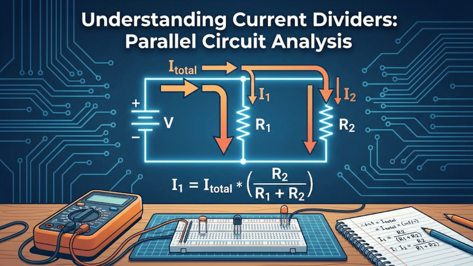
Simple two-resistor current divider:
        I_total
           ↓
     +-----+-----+
     |           |
    R₁          R₂
     |           |
    I₁          I₂
     |           |
+-----------+Total current I_total enters the junction, splits into I₁ and I₂, then recombines.
Key principle: I_total = I₁ + I₂ (Kirchhoff’s Current Law)
The Inverse Relationship
Current divides inversely proportional to resistance:
For two resistors:
- If R₁ = R₂, then I₁ = I₂ (equal resistance → equal current)
- If R₁ = 2×R₂, then I₁ = 0.5×I₂ (double resistance → half current)
- If R₁ = 0.5×R₂, then I₁ = 2×I₂ (half resistance → double current)
Mathematical relationship: I₁ / I₂ = R₂ / R₁ (currents ratio equals inverse of resistances ratio)
Example: I_total = 6A, R₁ = 2Ω, R₂ = 4Ω
Since R₂ = 2×R₁, we expect I₁ = 2×I₂
Verification: I₁ + I₂ = 6A I₁ = 2×I₂
Substituting: 2×I₂ + I₂ = 6A → 3×I₂ = 6A → I₂ = 2A Therefore: I₁ = 4A
Check: I₁/I₂ = 4A/2A = 2 = R₂/R₁ = 4Ω/2Ω ✓
Common Voltage, Divided Current
Fundamental parallel circuit property: All parallel branches have the same voltage across them.
Using Ohm’s Law on each branch:
- Branch 1: V = I₁ × R₁
- Branch 2: V = I₂ × R₂
Since V is the same for both: I₁ × R₁ = I₂ × R₂
Rearranging: I₁ / I₂ = R₂ / R₁
This proves the inverse relationship mathematically.
Difference from Voltage Dividers
Voltage divider (series circuit):
- Same current through all components
- Voltage divides proportionally to resistance
- Higher R gets more voltage
- V₁/V₂ = R₁/R₂ (direct proportion)
Current divider (parallel circuit):
- Same voltage across all components
- Current divides inversely to resistance
- Higher R gets less current
- I₁/I₂ = R₂/R₁ (inverse proportion)
Memory aid: “Series voltage rises with resistance, parallel current falls with resistance.”
The Current Divider Formula
Two-Resistor Current Divider
For exactly two resistors in parallel, the current through each resistor:
I₁ = I_total × (R₂ / (R₁ + R₂))
I₂ = I_total × (R₁ / (R₁ + R₂))
Key observation: Each resistor’s current uses the OTHER resistor in the numerator.
Example: I_total = 10A, R₁ = 30Ω, R₂ = 60Ω
I₁ = 10A × (60Ω / (30Ω + 60Ω)) = 10A × (60/90) = 6.67A I₂ = 10A × (30Ω / 90Ω) = 10A × (30/90) = 3.33A
Verification: I₁ + I₂ = 6.67A + 3.33A = 10A ✓
Deriving the Two-Resistor Formula
Given: I_total, R₁, R₂ in parallel
Step 1: Find voltage across parallel combination R_parallel = (R₁ × R₂) / (R₁ + R₂) V = I_total × R_parallel = I_total × (R₁ × R₂) / (R₁ + R₂)
Step 2: Apply Ohm’s Law to find I₁ I₁ = V / R₁ = [I_total × (R₁ × R₂) / (R₁ + R₂)] / R₁ I₁ = I_total × R₂ / (R₁ + R₂)
Step 3: Similarly for I₂ I₂ = V / R₂ = I_total × R₁ / (R₁ + R₂)
This derivation shows that current divider formula comes from combining Ohm’s Law with parallel resistance.
General Multi-Resistor Current Divider
For n resistors in parallel, current through resistor Rₙ:
I_n = I_total × (R_parallel / R_n)
Where R_parallel is the total parallel resistance of all resistors: 1/R_parallel = 1/R₁ + 1/R₂ + 1/R₃ + …
Example: Three resistors R₁ = 10Ω, R₂ = 20Ω, R₃ = 30Ω, I_total = 11A
Step 1: Calculate R_parallel 1/R_parallel = 1/10 + 1/20 + 1/30 = 0.1 + 0.05 + 0.033 = 0.183 R_parallel = 1/0.183 ≈ 5.45Ω
Step 2: Calculate each current I₁ = 11A × (5.45Ω / 10Ω) = 6.0A I₂ = 11A × (5.45Ω / 20Ω) = 3.0A I₃ = 11A × (5.45Ω / 30Ω) = 2.0A
Verification: I₁ + I₂ + I₃ = 6.0A + 3.0A + 2.0A = 11A ✓
Equal Resistors Special Case
When all n resistors have the same value R:
I_each = I_total / n
Current divides equally among equal resistors!
Example: I_total = 12A flowing through 4 equal 100Ω resistors I_each = 12A / 4 = 3A through each resistor
This is the simplest and most intuitive current division case.
Alternative Formula Using Conductance
Conductance (G) is the reciprocal of resistance: G = 1/R
Current divider using conductance: I_n = I_total × (G_n / G_total)
Where G_total = G₁ + G₂ + G₃ + …
Why this form makes sense: Current divides proportionally to conductance (ability to conduct), which is more intuitive than inverse proportion to resistance.
Example: R₁ = 10Ω (G₁ = 0.1 S), R₂ = 20Ω (G₂ = 0.05 S), I_total = 9A
G_total = 0.1 + 0.05 = 0.15 S I₁ = 9A × (0.1/0.15) = 6A I₂ = 9A × (0.05/0.15) = 3A
This is mathematically equivalent to the resistance-based formula but sometimes more intuitive.
Step-by-Step Current Divider Calculations
Example 1: Basic Two-Resistor Division
Problem: I_total = 5A, R₁ = 100Ω, R₂ = 400Ω Find I₁ and I₂.
Solution:
Method 1: Current divider formula I₁ = 5A × (400Ω / (100Ω + 400Ω)) = 5A × (400/500) = 4A I₂ = 5A × (100Ω / 500Ω) = 5A × (100/500) = 1A
Method 2: Using parallel resistance and Ohm’s Law R_parallel = (100Ω × 400Ω) / 500Ω = 80Ω V = 5A × 80Ω = 400V I₁ = 400V / 100Ω = 4A I₂ = 400V / 400Ω = 1A
Method 3: Using current ratio I₁/I₂ = R₂/R₁ = 400Ω/100Ω = 4 So I₁ = 4×I₂
Since I₁ + I₂ = 5A: 4×I₂ + I₂ = 5A → I₂ = 1A, I₁ = 4A
All three methods give the same answer!
Example 2: Three-Resistor Current Divider
Problem: I_total = 6A, R₁ = 12Ω, R₂ = 24Ω, R₃ = 48Ω Find current through each resistor.
Solution:
Step 1: Calculate total parallel resistance 1/R_parallel = 1/12 + 1/24 + 1/48 1/R_parallel = 4/48 + 2/48 + 1/48 = 7/48 R_parallel = 48/7 ≈ 6.86Ω
Step 2: Apply current divider formula I₁ = 6A × (6.86Ω / 12Ω) ≈ 3.43A I₂ = 6A × (6.86Ω / 24Ω) ≈ 1.72A I₃ = 6A × (6.86Ω / 48Ω) ≈ 0.86A
Verification: 3.43A + 1.72A + 0.86A ≈ 6.01A ≈ 6A ✓ (small rounding error)
Pattern observation: Notice that I₁ : I₂ : I₃ = 4 : 2 : 1 This matches the inverse of R₁ : R₂ : R₃ = 12 : 24 : 48 = 1 : 2 : 4
Example 3: Finding Unknown Resistance
Problem: I_total = 8A, R₁ = 20Ω, R₂ = unknown Measured: I₁ = 6A Find R₂ and I₂.
Solution:
Step 1: Find I₂ using KCL I₂ = I_total – I₁ = 8A – 6A = 2A
Step 2: Both resistors have same voltage V = I₁ × R₁ = 6A × 20Ω = 120V
Step 3: Calculate R₂ R₂ = V / I₂ = 120V / 2A = 60Ω
Verification using current ratio: I₁/I₂ = R₂/R₁ 6A/2A = R₂/20Ω 3 = R₂/20Ω R₂ = 60Ω ✓
Example 4: Current Division with Mixed Units
Problem: I_total = 500mA, R₁ = 1.5kΩ, R₂ = 3.3kΩ, R₃ = 4.7kΩ
Solution:
Step 1: Keep consistent units (work in mA and kΩ)
Step 2: Calculate parallel resistance 1/R_parallel = 1/1.5 + 1/3.3 + 1/4.7 (in kΩ) 1/R_parallel ≈ 0.667 + 0.303 + 0.213 = 1.183 kΩ⁻¹ R_parallel ≈ 0.845kΩ
Step 3: Calculate currents I₁ = 500mA × (0.845kΩ / 1.5kΩ) ≈ 281mA I₂ = 500mA × (0.845kΩ / 3.3kΩ) ≈ 128mA I₃ = 500mA × (0.845kΩ / 4.7kΩ) ≈ 90mA
Verification: 281 + 128 + 90 = 499mA ≈ 500mA ✓
Example 5: Practical LED Circuit
Problem: Three LEDs in parallel, each with current-limiting resistor:
- LED1 with R₁ = 330Ω
- LED2 with R₂ = 330Ω
- LED3 with R₃ = 470Ω Total current available: 60mA Approximate current through each LED?
Assumption: LEDs all drop approximately 2V when conducting.
Solution:
Step 1: Calculate effective resistance of each branch Each branch = LED voltage drop + resistor All LEDs drop ~2V, so current is determined by resistors.
Step 2: Apply current divider (approximately) Treating as pure resistive divider (rough approximation):
1/R_eq = 1/330 + 1/330 + 1/470 1/R_eq ≈ 0.00303 + 0.00303 + 0.00213 = 0.00819 Ω⁻¹ R_eq ≈ 122Ω
I₁ = 60mA × (122/330) ≈ 22.2mA I₂ = 60mA × (122/330) ≈ 22.2mA I₃ = 60mA × (122/470) ≈ 15.6mA
Note: This is approximate because LEDs aren’t pure resistors. Real analysis requires accounting for LED voltage drop and nonlinear characteristics.
Practical Applications of Current Dividers
Application 1: Parallel LED Strings
Scenario: Driving multiple LED strings from one current source.
Circuit:
Current Source (60mA)
      ↓
  +---+---+---+
  |   |   |   |
 LED LED LED LED
  |   |   |   |
 330Ω 330Ω 470Ω 560Ω
  |   |   |   |
  +---+---+---+
      ↓
     GND
Current division: Each branch receives current inversely proportional to its total resistance (LED + resistor).
Why useful:
- Allows driving multiple LEDs from single current source
- Each branch can have different resistor for brightness control
- If one LED fails open, others continue working (unlike series)
Design consideration: Use individual resistors per LED to ensure current balancing despite LED voltage variations.
Application 2: Current Sensing with Shunt Resistors
Scenario: Measuring high current with low-value shunt resistor.
Circuit:
Load (draws 10A)
      ↓
  +-------+
  |       |
 0.01Ω   1MΩ to voltmeter
 shunt    |
  |       |
+-------+Current division: I_shunt ≈ 10A (essentially all current) I_voltmeter ≈ 0V/1MΩ ≈ negligible
Why this works: The shunt resistance (0.01Ω) is so much smaller than the voltmeter input (1MΩ) that virtually all current flows through the shunt. The voltmeter measures voltage across the shunt with minimal loading.
Voltage across shunt: V = 10A × 0.01Ω = 0.1V (measurable)
Actual current division: R_parallel = (0.01Ω × 1MΩ) / (0.01Ω + 1MΩ) ≈ 0.01Ω I_shunt = 10A × (almost 1) = ~10A I_meter = 10A × (0.01Ω / 1MΩ) = 0.1μA (negligible)
Application 3: Multi-Battery Parallel Charging
Scenario: Two batteries in parallel being charged.
Important: Batteries have internal resistance!
Example:
- Battery 1: 12V, 0.1Ω internal resistance
- Battery 2: 12V, 0.15Ω internal resistance
- Charger supplies 5A total
Current division: I₁ = 5A × (0.15Ω / (0.1Ω + 0.15Ω)) = 5A × 0.6 = 3A to Battery 1 I₂ = 5A × (0.1Ω / 0.25Ω) = 5A × 0.4 = 2A to Battery 2
Result: Battery 1 (lower internal resistance) receives more current.
Implication: Batteries with different internal resistances charge at different rates when paralleled. This is why battery management systems are important!
Application 4: Ammeter Range Extension
Scenario: Extend ammeter range using shunt resistor.
Problem: Meter movement has 1mA full-scale, 50Ω internal resistance. Want to measure 0-1A.
Solution: Add shunt resistor in parallel to divert most current around the meter.
Design: Want meter to show full scale (1mA) when total current is 1A. Current through shunt: 1A – 1mA = 999mA
Using current divider (inverse proportion): I_meter / I_shunt = R_shunt / R_meter 1mA / 999mA = R_shunt / 50Ω R_shunt = 50Ω × (1/999) ≈ 0.05Ω
Verification: R_parallel = (50Ω × 0.05Ω) / (50.05Ω) ≈ 0.0499Ω At 1A total: I_meter = 1A × (0.0499Ω / 50Ω) ≈ 1mA ✓
Application 5: Signal Splitting in Analog Circuits
Scenario: Split audio signal to multiple destinations.
Circuit:
Signal Source (low impedance)
      ↓
  +---+---+
  |   |   |
 10kΩ 10kΩ 10kΩ (to different circuits)
  |   |   |
+---+---+Current division: Equal resistors → Equal current to each destination
If source provides 1mA signal current: Each path receives: 1mA / 3 = 0.333mA
Consideration: Source impedance and load impedances affect actual division. This is simplified example.
Application 6: Current Balancing in Parallel Voltage Regulators
Scenario: Two voltage regulators in parallel for higher current capacity.
Problem: Without current sharing, one regulator may carry most of the load.
Solution: Add small resistors in series with each regulator output to create current-sharing network.
Example: Two 5V/1A regulators with 0.1Ω resistors:
If load draws 1.8A total and one regulator tries to supply more:
- The increased current through its resistor creates larger voltage drop
- This reduces voltage at that regulator’s output
- Less voltage means it supplies less current
- System self-balances
This uses current divider principles to enforce equal current sharing.
Current Dividers vs. Voltage Dividers: Key Differences
Fundamental Contrast
Topology:
- Voltage divider: Series configuration
- Current divider: Parallel configuration
What divides:
- Voltage divider: Voltage splits among components
- Current divider: Current splits among components
What’s constant:
- Voltage divider: Same current through all resistors
- Current divider: Same voltage across all resistors
Division relationship:
- Voltage divider: Voltage proportional to resistance (direct)
- Current divider: Current inversely proportional to resistance (inverse)
Mathematical Comparison
Voltage divider: V_out = V_in × (R₂ / (R₁ + R₂)) Higher R₂ → Higher V_out
Current divider: I_out = I_in × (R_other / (R_this + R_other)) Higher R_this → Lower I_out
Notice: Formulas look similar but work oppositely!
Practical Usage Comparison
When to use voltage divider:
- Scale voltage for ADC input
- Create reference voltages
- Sensor interfacing (resistive sensors)
- Bias points for transistors
When to use current divider:
- Divide current among parallel loads
- Current sensing circuits
- Parallel LED strings
- Battery balancing
- Signal distribution
Loading Effects
Voltage divider: Load appears in parallel with bottom resistor Effect: Reduces output voltage
Current divider: Load draws current from one branch Effect: Changes current distribution
Design Considerations
Voltage divider:
- Output impedance = R₁ || R₂
- Lower resistances → Lower output impedance, higher power
- Choose values based on load impedance (10× rule)
Current divider:
- All branches must handle their current
- Total power = sum of power in all branches
- Choose values based on desired current split
Common Mistakes and Misconceptions
Mistake 1: Confusing Current and Voltage Division
Error: Thinking higher resistance gets more current (mixing up voltage divider behavior).
Example of error: R₁ = 10Ω, R₂ = 20Ω, I_total = 6A Wrong thinking: “R₂ is larger, so I₂ > I₁” Wrong answer: I₂ = 4A, I₁ = 2A
Correct: Higher resistance gets less current! I₁ = 6A × (20Ω/30Ω) = 4A I₂ = 6A × (10Ω/30Ω) = 2A
How to avoid: Remember the inverse relationship—current takes the path of least resistance.
Mistake 2: Using Wrong Formula
Error: Using voltage divider formula for current divider.
Example of error: Trying to calculate I₁ with: I₁ = I_total × (R₁/(R₁+R₂))
This is wrong! This would be the voltage divider formula applied incorrectly.
Correct: I₁ = I_total × (R₂/(R₁+R₂)) Notice: OTHER resistor in numerator!
Mistake 3: Ignoring KCL
Error: Calculating branch currents without verifying they sum to total current.
Always check: I₁ + I₂ + I₃ + … = I_total
If they don’t sum correctly, you made a calculation error.
Mistake 4: Forgetting About Component Tolerances
Error: Assuming exact current division with real components.
Reality: Resistor tolerances (typically ±5%) cause current division variations.
Example: Design: R₁ = R₂ = 100Ω (expecting equal current split) Reality: R₁ = 95Ω, R₂ = 105Ω (within 5% tolerance)
Expected: I₁ = I₂ = I_total/2 Actual: I₁ = I_total × (105/200) = 0.525 × I_total I₂ = I_total × (95/200) = 0.475 × I_total
10% difference in current split!
Solution: Use precision resistors (1% or better) when accurate current division is critical.
Mistake 5: Not Accounting for Component Power Ratings
Error: Calculating currents without checking if resistors can handle the power.
Example: I_total = 2A, R₁ = R₂ = 10Ω I₁ = I₂ = 1A (equal division)
Power per resistor: P = I² × R = (1A)² × 10Ω = 10W
If you used 1/4W resistors, they’d instantly fail!
Always calculate: P = I² × R for each branch resistor and verify against power rating.
Mistake 6: Applying Current Divider to Non-Resistive Components
Error: Using current divider formula with LEDs, diodes, or other non-ohmic components.
Problem: LEDs, diodes, etc. don’t have constant resistance—they have voltage-current curves.
Example: Two LEDs in parallel (no resistors):
- Both have ~2V forward voltage
- Current doesn’t divide by resistance formula
- Instead, current divides based on LED characteristics and slight voltage differences
Reality: Small voltage differences cause large current imbalances.
Solution: Always use individual current-limiting resistors with parallel LEDs to enforce predictable current division.
Mistake 7: Mixing Impedances at Different Frequencies
Error: Using DC resistance values for AC current division without considering frequency effects.
Reality: At AC frequencies, capacitors and inductors have impedance that varies with frequency.
Example: Parallel RC circuit:
- 1kΩ resistor
- 1μF capacitor
- At DC: Capacitor = infinite impedance (all current through resistor)
- At 160Hz: Capacitor = 1kΩ impedance (equal current split)
- At 16kHz: Capacitor = 10Ω impedance (most current through capacitor)
Solution: Use impedance (Z) instead of resistance (R) for AC current division.
Advanced Topics
Current Division with Impedances (AC Circuits)
For AC circuits with capacitors, inductors, or complex impedances:
Formula: I_n = I_total × (Z_parallel / Z_n)
Where Z represents complex impedance: Z = R + jX
Example: Parallel RC circuit with 10mA AC current at 1kHz:
- R = 1kΩ
- C = 0.1μF (X_C = 1/(2πfC) ≈ 1.59kΩ)
Z_R = 1000Ω (purely resistive) Z_C = -j1590Ω (capacitive reactance)
Z_parallel = (Z_R × Z_C) / (Z_R + Z_C)
This requires complex number arithmetic, beyond basic current divider analysis.
Current Division with Current Sources
Ideal current source: Provides constant current regardless of voltage.
Two current sources in parallel: I_total = I_source1 + I_source2
Currents add directly! (Both sources inject current into the same node)
Current source parallel with resistor: The resistor determines voltage, current source determines current through its branch.
Non-Ideal Current Sources
Real current sources have finite output impedance (resistance in parallel with ideal source).
Example: Current source: 10mA, output impedance 100kΩ Parallel load: 10kΩ
Current division between source impedance and load: I_load = 10mA × (100kΩ / 110kΩ) ≈ 9.09mA I_source_impedance = 10mA × (10kΩ / 110kΩ) ≈ 0.91mA
Most current goes to load (desired), small amount through source impedance.
Temperature Effects on Current Division
Resistor temperature coefficients: Resistances change with temperature.
Example: Two 1kΩ resistors with different temperature coefficients:
- R₁: 100 ppm/°C
- R₂: 50 ppm/°C
At 25°C: Equal current division At 75°C (50°C rise):
- R₁ changes by: 1000Ω × 100 × 10⁻⁶ × 50 = 5Ω → 1005Ω
- R₂ changes by: 1000Ω × 50 × 10⁻⁶ × 50 = 2.5Ω → 1002.5Ω
Current ratio changes: I₁/I₂ = R₂/R₁ = 1002.5/1005 ≈ 0.9975
Small effect, but matters in precision applications.
Solution: Use resistors with matched temperature coefficients for precision current division.
Comparison Table: Current Divider Characteristics
| Aspect | Two Equal Resistors | Two Unequal Resistors | Three or More Resistors | With Impedances (AC) |
|---|---|---|---|---|
| Current split | 50/50 (equal) | Inverse to resistance ratio | Calculate using R_parallel | Depends on frequency |
| Calculation complexity | Very simple (divide by 2) | Simple formula | Moderate (need R_parallel) | Complex (requires phasors) |
| Formula | I_each = I_total / 2 | I₁ = I_total × R₂/(R₁+R₂) | I_n = I_total × R_parallel/R_n | I_n = I_total × Z_parallel/Z_n |
| Sensitivity to tolerance | Low (averages out) | Moderate | Higher (more components) | Varies with frequency |
| Typical applications | Signal splitting, load balancing | Current sensing, LED strings | Multi-load circuits | Audio, RF circuits |
| Power distribution | Equal in each branch | Higher power in lower R | Sum of all branches | Depends on phase angles |
| Design difficulty | Trivial | Easy | Moderate | Advanced |
| Accuracy | Excellent | Good | Fair (tolerances stack) | Depends on component Q |
| Component matching | Not critical | Moderate importance | Important | Critical |
Practical Design Guidelines
Design Checklist for Current Dividers
1. Define requirements:
- [ ] What is total available current?
- [ ] What current split ratio is needed?
- [ ] What tolerance is acceptable?
- [ ] What power dissipation is acceptable?
2. Calculate resistor values:
- [ ] Use current divider formula to determine ratios
- [ ] Select standard resistor values
- [ ] Verify current split with standard values
3. Verify power ratings:
- [ ] Calculate I² × R for each branch
- [ ] Select resistors with adequate power rating (2× safety margin minimum)
- [ ] Consider thermal design if power is significant
4. Consider tolerances:
- [ ] Calculate worst-case current split with component tolerances
- [ ] Use tighter tolerance resistors if needed (1% vs. 5%)
- [ ] Consider calibration or adjustment if critical
5. Check for special considerations:
- [ ] Are loads resistive or do they have voltage requirements? (like LEDs)
- [ ] Is frequency response important? (AC vs. DC)
- [ ] Are temperature variations significant?
- [ ] Could component failure modes cause problems?
Rules of Thumb
Equal division: Use equal resistors (simplest, most tolerant)
2:1 division: R₁:R₂ = 1:2 ratio gives I₁:I₂ = 2:1 current ratio
10:1 division: R₁:R₂ = 1:10 ratio gives approximately 10:1 current ratio
- 91% through lower resistance
- 9% through higher resistance
For precision (<5% error): Use 1% tolerance resistors
For approximate division (±20% acceptable): Standard 5% resistors sufficient
Power safety: Derate to 50% of resistor power rating for reliability
When to Use Current Dividers
Good applications: ✓ Dividing current among parallel loads ✓ Current sensing with shunts ✓ LED arrays with individual resistors ✓ Parallel battery charging (with management) ✓ Analog signal distribution ✓ Ammeter range extension
Poor applications: ✗ Precision current sources (use active circuits instead) ✗ Very high currents (losses in resistors) ✗ When efficiency is critical (resistive losses) ✗ With highly nonlinear components (without series resistors)
Troubleshooting Current Divider Circuits
Problem 1: Uneven Current Distribution
Symptoms: Branch currents don’t match calculations.
Possible causes:
- Wrong resistor values installed
- Resistor tolerances larger than expected
- Temperature effects changing resistances
- Faulty components
Diagnosis:
- Measure each resistor with ohmmeter (out of circuit)
- Calculate expected currents with measured values
- Compare to measured currents
- Check for heating (indicates high power dissipation)
Solutions:
- Replace with correct value resistors
- Use tighter tolerance components
- Adjust for temperature or improve cooling
- Replace faulty components
Problem 2: One Branch Carries No Current
Symptoms: Current only flows through some branches.
Possible causes:
- Open circuit in dead branch (broken connection, failed resistor)
- Very high resistance in that branch
- Shorted component in other branch(es)
Diagnosis:
- Check for voltage across dead branch (should match other branches if parallel)
- If no voltage → Problem with connections to that branch
- If voltage present → Check for open circuit in branch
Solutions:
- Repair connections
- Replace open components
- Fix shorts in other branches
Problem 3: Excessive Power Dissipation
Symptoms: Resistors getting hot, possible failure.
Causes:
- Total current higher than expected
- Resistor power rating too low
- Inadequate cooling
Solutions:
- Verify total current is within design limits
- Use higher power rating resistors
- Use multiple parallel resistors to distribute power
- Add heat sinking or forced air cooling
Conclusion: Mastering Parallel Current Division
Current dividers represent the parallel circuit complement to voltage dividers, providing a systematic way to understand and design circuits where current splits among multiple branches. While less famous than their voltage divider cousins, current dividers are equally fundamental to circuit analysis and design.
Key Principles Revisited
The inverse relationship is the heart of current division: higher resistance gets less current, lower resistance gets more current. This is opposite to voltage division, where higher resistance gets more voltage.
The current divider formula I_n = I_total × (R_other / (R_this + R_other)) for two resistors, or the general form using parallel resistance, provides the mathematical tool for calculating current distribution.
Kirchhoff’s Current Law underlies all current division: the sum of branch currents must equal the total current entering the junction.
Practical Takeaways
Current dividers appear throughout electronics:
- Parallel LED strings use current division
- Shunt resistor current sensing relies on current division
- Battery balancing involves current division among cells
- Signal splitting circuits divide current among paths
Understanding current division enables you to:
- Design circuits that split current predictably
- Size components appropriately for current and power
- Troubleshoot parallel circuit problems
- Develop intuition about parallel circuit behavior
The Bigger Picture
Current dividers and voltage dividers together form the foundation of passive circuit analysis:
- Series circuits (voltage dividers): Constant current, divided voltage
- Parallel circuits (current dividers): Constant voltage, divided current
- Series-parallel combinations: Use both principles together
Mastering both concepts gives you the tools to analyze any resistive network, no matter how complex.
Moving Forward
With current division understood:
- You can analyze parallel circuits confidently
- You understand why “current takes the path of least resistance”
- You can design practical current-splitting circuits
- You’re prepared for more advanced topics like impedance and AC analysis
The journey from basic Ohm’s Law through series circuits, parallel circuits, voltage dividers, and current dividers builds a comprehensive understanding of DC circuit behavior. Each concept reinforces the others, creating a coherent framework for circuit analysis.
Current dividers: where current splits, physics determines the division, and engineering harnesses it for practical purposes.