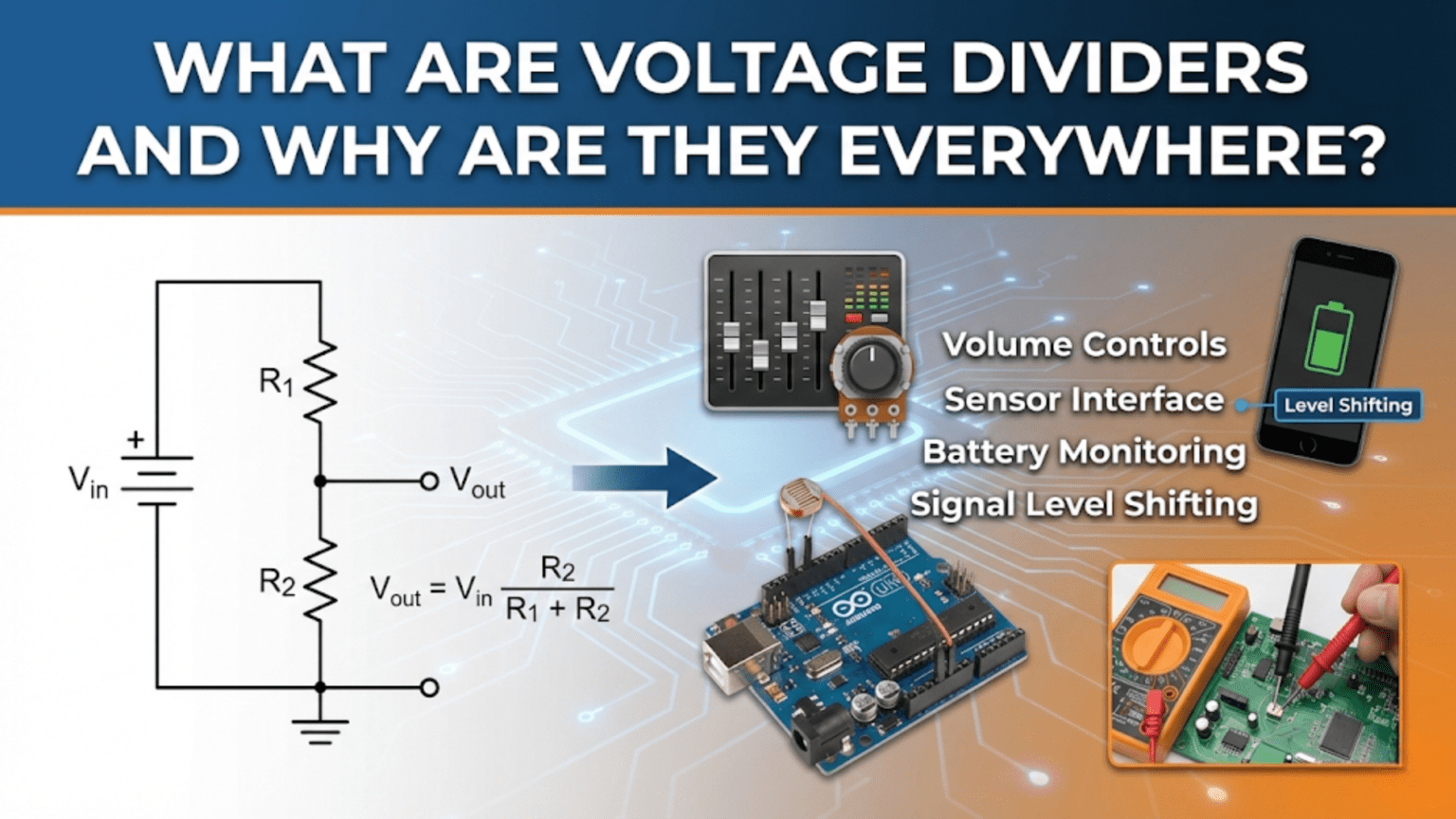
A voltage divider is a simple circuit consisting of two or more resistors in series across a voltage source, producing an output voltage that is a fraction of the input voltage based on the resistor ratio. Voltage dividers are everywhere in electronics because they provide the simplest method to scale voltages for analog-to-digital conversion, create reference voltages, set bias points for transistors, read resistive sensors, interface between different voltage levels, and perform countless other essential functions in virtually every electronic device.
Introduction: The Circuit That’s Hiding in Plain Sight
Open any electronic device—a smartphone, laptop, television, car dashboard, or even a simple battery-powered toy—and you’ll find voltage dividers. Dozens of them. Sometimes hundreds. They’re so fundamental to electronics that most circuit designers use them without conscious thought, yet many beginners overlook this simple but powerful configuration.
A voltage divider is elegant in its simplicity: just two resistors in series across a voltage source, with the output taken from the junction between them. Yet this basic arrangement solves countless design challenges. Need to measure a 12V battery with a microcontroller that only accepts 5V inputs? Voltage divider. Want to read the position of a potentiometer or the value of a thermistor? Voltage divider. Need to set the bias voltage for a transistor amplifier? Voltage divider. Creating a reference voltage for a comparator? Voltage divider.
The ubiquity of voltage dividers stems from their versatility. They scale voltages proportionally, convert resistance changes to voltage changes, create stable reference points, and interface between different voltage domains—all with just passive components that never fail, never need power themselves, and cost pennies. In an era of complex integrated circuits and sophisticated digital systems, the humble voltage divider remains indispensable.
Understanding voltage dividers is essential for anyone working with electronics. Beyond just knowing the formula, you need to understand how loading affects output voltage, when voltage dividers are appropriate versus when other solutions are better, how to select resistor values for different applications, and how to troubleshoot when dividers don’t behave as expected.
This comprehensive guide will take you from the fundamental concepts through advanced applications. We’ll explore the mathematics behind voltage division, examine the critical concept of loading, work through practical design examples, investigate real-world applications across different domains, learn when not to use voltage dividers, and develop the intuition needed to apply this essential circuit effectively.
Whether you’re just beginning your electronics journey or deepening your understanding of fundamental circuits, mastering voltage dividers will serve you throughout your entire career in electronics. Let’s explore why this simple circuit appears everywhere and how to use it effectively.
The Voltage Divider Principle
The Basic Configuration
A voltage divider consists of:
- Input voltage (V_in): Applied across the series combination
- Two resistors in series: R₁ (top resistor) and R₂ (bottom resistor)
- Output voltage (V_out): Taken from the junction between R₁ and R₂
V_in ----[R₁]----+---- V_out
                 |
               [R₂]
                 |
GND (0V)The output voltage is a fraction of the input voltage, determined by the resistor ratio.
The Voltage Divider Formula
The fundamental equation for voltage dividers:
V_out = V_in × (R₂ / (R₁ + R₂))
Where:
- V_out is the output voltage at the junction
- V_in is the input voltage across the entire series chain
- R₁ is the resistor from V_in to V_out (top resistor)
- R₂ is the resistor from V_out to ground (bottom resistor)
Alternative form: V_out = V_in × (R₂ / R_total)
Where R_total = R₁ + R₂
Key insight: The output voltage is the input voltage multiplied by the fraction that R₂ represents of the total resistance.
Deriving the Formula
The voltage divider formula comes directly from Ohm’s Law and Kirchhoff’s Voltage Law:
Step 1: Find total resistance R_total = R₁ + R₂ (series resistors add)
Step 2: Calculate current through series circuit I = V_in / R_total (Ohm’s Law applied to entire circuit)
Step 3: Find voltage across R₂ V_out = I × R₂ (Ohm’s Law applied to R₂)
Step 4: Substitute current from Step 2 V_out = (V_in / R_total) × R₂ V_out = V_in × (R₂ / R_total) V_out = V_in × (R₂ / (R₁ + R₂))
This derivation shows that voltage division is just a combination of series resistance and Ohm’s Law—nothing mysterious, just fundamental circuit principles working together.
Understanding the Ratio
The voltage divider equation tells us that output voltage depends only on the resistor ratio, not their absolute values (assuming no load):
Example 1: R₁ = 1kΩ, R₂ = 1kΩ Ratio: R₂/(R₁+R₂) = 1kΩ/2kΩ = 0.5 V_out = 0.5 × V_in
Example 2: R₁ = 10kΩ, R₂ = 10kΩ Ratio: R₂/(R₁+R₂) = 10kΩ/20kΩ = 0.5 V_out = 0.5 × V_in
Same ratio, same output voltage! (We’ll see why absolute values matter when we discuss loading.)
Different ratios:
- R₁ = 2kΩ, R₂ = 1kΩ → Ratio = 1/3 → V_out = V_in/3
- R₁ = 1kΩ, R₂ = 3kΩ → Ratio = 3/4 → V_out = 0.75 × V_in
- R₁ = 9kΩ, R₂ = 1kΩ → Ratio = 1/10 → V_out = V_in/10
Quick Mental Calculations
For equal resistors: V_out = V_in/2 (divide by number of equal resistors for the bottom one)
For simple ratios:
- 1:1 ratio → V_out = V_in/2
- 1:2 ratio → V_out = 2V_in/3 (R₂ is 2× larger)
- 1:3 ratio → V_out = 3V_in/4 (R₂ is 3× larger)
- 1:9 ratio → V_out = 9V_in/10 (R₂ is 9× larger)
Pattern recognition: If R₂ is n times larger than R₁: V_out = V_in × (n/(n+1))
Why Voltage Dividers Are Everywhere
Application 1: Analog-to-Digital Conversion (ADC) Scaling
The problem: You want to measure a 12V battery with a microcontroller that has a 5V maximum ADC input.
The solution: Voltage divider that scales 12V → 5V (or less for safety margin).
Design: Want V_out = 4.5V when V_in = 12V (leaving 0.5V safety margin)
Ratio needed: 4.5V/12V = 0.375
R₂/(R₁+R₂) = 0.375 R₂ = 0.375(R₁+R₂) R₂ = 0.375R₁ + 0.375R₂ 0.625R₂ = 0.375R₁ R₂/R₁ = 0.375/0.625 = 0.6
Choose R₁ = 10kΩ, then R₂ = 6kΩ (use 5.6kΩ or 6.2kΩ standard value)
Verification with 5.6kΩ: V_out = 12V × (5.6kΩ/(10kΩ+5.6kΩ)) = 12V × 0.359 ≈ 4.31V ✓
This simple divider allows the microcontroller to monitor battery voltage safely.
Application 2: Resistive Sensor Reading
The problem: A photoresistor varies from 1kΩ (bright light) to 100kΩ (darkness). How do you convert this resistance change to a voltage your microcontroller can read?
The solution: Voltage divider with photoresistor as one of the resistors.
Configuration:
5V ----[Photoresistor]----+---- V_out to ADC
                          |
                        [10kΩ]
                          |
GNDBehavior:
- Bright (1kΩ): V_out = 5V × (10kΩ/11kΩ) ≈ 4.55V
- Dark (100kΩ): V_out = 5V × (10kΩ/110kΩ) ≈ 0.45V
The voltage varies from 0.45V to 4.55V as light changes, easily readable by ADC.
Why this works: Resistance changes in one resistor change the voltage division ratio, converting resistance to voltage.
Application 3: Biasing Transistor Circuits
The problem: A transistor amplifier needs its base at 2V for proper operation. Supply voltage is 9V.
The solution: Voltage divider to create the 2V bias point.
Design: Want 2V from 9V input: Ratio = 2V/9V ≈ 0.222
R₂/(R₁+R₂) = 0.222
Choose R₁ = 33kΩ, R₂ = 10kΩ: V_out = 9V × (10kΩ/43kΩ) ≈ 2.09V ✓
Why everywhere: Every transistor amplifier needs bias voltage, making voltage dividers essential in analog circuits.
Application 4: Reference Voltage Generation
The problem: A comparator needs a reference voltage of 3.3V. Supply is 5V.
The solution: Voltage divider creates stable 3.3V reference.
Design: Ratio = 3.3V/5V = 0.66
Choose R₁ = 1.7kΩ, R₂ = 3.3kΩ: V_out = 5V × (3.3kΩ/5kΩ) = 3.3V ✓
The comparator compares input signal against this 3.3V reference to make binary decisions.
Application 5: Level Shifting for Logic Interfaces
The problem: 5V logic output needs to connect to 3.3V logic input.
The solution: Voltage divider scales 5V → 3.3V.
Design: High level: 5V → 3.3V Low level: 0V → 0V
Ratio = 3.3V/5V = 0.66
R₁ = 1kΩ, R₂ = 2kΩ: V_out = 5V × (2kΩ/3kΩ) ≈ 3.33V ✓
Important: This only works if the 3.3V input has high impedance (doesn’t draw significant current).
Application 6: Potentiometer Applications
The universal voltage divider: A potentiometer is a variable voltage divider!
Configuration:
V_in ---- [   POT   ] ---- 0V
                |
V_out (wiper)Rotating the potentiometer changes the ratio between top and bottom resistances, varying V_out from 0V to V_in.
Applications:
- Volume controls (audio voltage adjustment)
- Brightness controls (LED driver voltage)
- User adjustments (calibration, tuning)
- Position sensing (mechanical position → voltage)
Application 7: Battery Monitoring Circuits
The problem: Monitor a 3-cell lithium battery (12.6V max) with 5V-capable monitoring IC.
The solution: Voltage divider scales battery voltage to IC’s range.
Design: Max input: 12.6V Max output (safe): 4.5V Ratio = 4.5V/12.6V ≈ 0.357
R₁ = 18kΩ, R₂ = 10kΩ: At 12.6V: V_out = 12.6V × (10kΩ/28kΩ) = 4.5V ✓ At 9.0V (discharged): V_out = 9V × (10kΩ/28kΩ) ≈ 3.21V
The IC can accurately monitor battery voltage across its entire range.
The Critical Concept: Loading Effects
What is Loading?
When you connect anything to a voltage divider’s output, that load appears in parallel with R₂, changing the effective resistance and therefore the output voltage.
Unloaded voltage divider:
V_in ----[R₁]----+---- V_out (theoretical)
                 |
               [R₂]
                 |
GNDLoaded voltage divider:
V_in ----[R₁]----+---- V_out (actual)
                 |
               [R₂] || [R_load]
                 |
GNDThe effective R₂ becomes: R₂ || R_load = (R₂ × R_load)/(R₂ + R_load)
This is always less than R₂, so V_out decreases when loaded!
Calculating Loaded Output Voltage
Step 1: Calculate effective R₂ R₂_effective = (R₂ × R_load)/(R₂ + R_load)
Step 2: Use voltage divider formula with effective resistance V_out_loaded = V_in × (R₂_effective/(R₁ + R₂_effective))
Example: Unloaded: R₁ = 10kΩ, R₂ = 10kΩ, V_in = 10V V_out = 10V × (10kΩ/20kΩ) = 5V
Loaded with R_load = 10kΩ: R₂_effective = (10kΩ × 10kΩ)/(10kΩ + 10kΩ) = 5kΩ V_out_loaded = 10V × (5kΩ/15kΩ) ≈ 3.33V
The output dropped from 5V to 3.33V due to loading! (33% error)
The 10× Rule for Negligible Loading
Design guideline: For less than 10% error from loading, the load resistance should be at least 10 times the bottom resistor (R₂).
R_load ≥ 10 × R₂
Example: R₂ = 10kΩ Minimum R_load for <10% error: 100kΩ
Verification: R₂_effective = (10kΩ × 100kΩ)/(110kΩ) ≈ 9.09kΩ Error: (10kΩ – 9.09kΩ)/10kΩ ≈ 9.1% ✓
Typical microcontroller ADC input: 10kΩ to 1MΩ (high impedance, minimal loading) Typical LED (with current): <100Ω (low impedance, severe loading) Op-amp input: >1MΩ (virtually no loading)
Choosing Resistor Values to Minimize Loading
Two competing concerns:
- Higher resistance values: Less current, less power, but more susceptible to loading
- Lower resistance values: Less affected by loading, but higher current and power consumption
Strategy: Choose resistors as high as possible while ensuring R_load >> R₂.
Example for ADC with 100kΩ input impedance: Want R_load = 10 × R₂ 100kΩ = 10 × R₂ R₂ = 10kΩ (maximum)
For 1:1 divider: R₁ = 10kΩ, R₂ = 10kΩ
Power consumption check: I = V_in/(R₁+R₂) = 10V/20kΩ = 0.5mA P = V × I = 10V × 0.5mA = 5mW (acceptable for most applications)
Buffer Amplifiers to Eliminate Loading
Problem: Load impedance is too low, causing unacceptable voltage division error.
Solution: Insert a buffer amplifier (voltage follower) between divider and load.
Configuration:
V_in ----[R₁]----+---- V_out_divider ----[Buffer Amp]---- V_out_buffered ---- Load
                 |
               [R₂]
                 |
GNDBuffer characteristics:
- Very high input impedance (>1MΩ typically)
- Very low output impedance (<100Ω typically)
- Unity gain (V_out = V_in)
Result: Divider “sees” only the buffer’s high input impedance (minimal loading), while the load “sees” the buffer’s low output impedance (can drive low-impedance loads).
Common buffer ICs:
- Op-amps configured as voltage followers
- Dedicated buffer ICs (e.g., LM358, TL071)
- Emitter/source follower transistor configurations
Practical Design Examples
Example 1: Battery Voltage Monitor for Arduino
Requirements:
- Monitor 9V battery (full: 9V, empty: 6V)
- Arduino ADC: 0-5V input, 10-bit resolution (1024 levels)
- Accuracy: ±0.1V
- Low power consumption
Design Process:
Step 1: Determine scaling ratio Maximum safe input to Arduino: 4.5V (leaving 0.5V margin) At 9V battery: V_out = 4.5V Ratio = 4.5V/9V = 0.5
Step 2: Select resistor values For 0.5 ratio: R₂ = R₁ Arduino ADC impedance: ~100kΩ (high, minimal loading)
Choose R₁ = R₂ = 10kΩ (follows 10× rule: 100kΩ > 10×10kΩ)
Step 3: Verify voltage range At 9V: V_out = 9V × 0.5 = 4.5V ✓ At 6V: V_out = 6V × 0.5 = 3.0V ✓
Step 4: Check resolution Voltage range: 3.0V to 4.5V = 1.5V span ADC resolution: 5V/1024 ≈ 4.9mV per step Voltage resolution: 4.9mV × 2 (due to divider) ≈ 9.8mV
Easily meets ±0.1V (±100mV) requirement.
Step 5: Calculate power consumption I = V/(R₁+R₂) = 9V/20kΩ = 0.45mA P = 9V × 0.45mA ≈ 4mW (very low)
Final design: R₁ = 10kΩ, R₂ = 10kΩ
Example 2: Thermistor Temperature Sensor
Requirements:
- NTC thermistor: 10kΩ at 25°C
- Temperature range: 0°C to 50°C
- Thermistor range: ~27kΩ (0°C) to ~4kΩ (50°C)
- Convert to voltage for 5V ADC
- Maximize voltage swing for best resolution
Design Process:
Step 1: Determine configuration
5V ----[10kΩ fixed]----+---- V_out
                       |
                   [Thermistor]
                       |
GNDAlternative: Thermistor on top, fixed resistor on bottom.
Step 2: Calculate voltage at temperature extremes
At 0°C (R_therm = 27kΩ): V_out = 5V × (27kΩ/(10kΩ+27kΩ)) = 5V × 0.73 ≈ 3.65V
At 50°C (R_therm = 4kΩ): V_out = 5V × (4kΩ/(10kΩ+4kΩ)) = 5V × 0.286 ≈ 1.43V
Voltage swing: 3.65V – 1.43V = 2.22V
Step 3: Consider alternative with thermistor on top
5V ----[Thermistor]----+---- V_out
                       |
                     [10kΩ]
                       |
GNDAt 0°C: V_out = 5V × (10kΩ/37kΩ) ≈ 1.35V At 50°C: V_out = 5V × (10kΩ/14kΩ) ≈ 3.57V
Voltage swing: 3.57V – 1.35V = 2.22V (same span, but inverted relationship)
Step 4: Choose configuration based on desired polarity
- Thermistor on bottom: Voltage increases with temperature
- Thermistor on top: Voltage decreases with temperature
Choose based on software preference or circuit requirements.
Example 3: Precision Reference for Comparator
Requirements:
- Reference voltage: 2.500V ±0.01V (±0.4%)
- Input voltage: 5.000V ±0.05V (regulated supply)
- Load: Comparator input (very high impedance, ~10MΩ)
- Temperature stable
Design Process:
Step 1: Calculate basic ratio Ratio = 2.500V/5.000V = 0.5 exactly
Step 2: Select precision resistors Need matched tolerance to achieve 0.4% output accuracy.
For 0.5 ratio with 0.4% accuracy: Use 0.1% tolerance resistors
R₁ = R₂ = 10kΩ (0.1% tolerance)
Step 3: Tolerance analysis Worst case (both resistors at opposite tolerance extremes): R₁ = 10.01kΩ, R₂ = 9.99kΩ V_out = 5V × (9.99kΩ/20kΩ) = 2.4975V (-0.1% from ideal)
Or: R₁ = 9.99kΩ, R₂ = 10.01kΩ V_out = 5V × (10.01kΩ/20kΩ) = 2.5025V (+0.1% from ideal)
Combined with ±0.05V supply tolerance: At 5.05V: V_out = 2.525V to 2.5275V At 4.95V: V_out = 2.4725V to 2.475V
Total range: 2.4725V to 2.5275V (±0.55% from ideal 2.500V)
This doesn’t meet ±0.4% requirement!
Step 4: Use tighter tolerance or voltage reference
Option A: 0.05% resistors would give ±0.05% accuracy, meeting requirement.
Option B: Use dedicated voltage reference IC (e.g., TL431) set to exactly 2.500V, eliminating resistor tolerance issues.
For this precision application: Use voltage reference IC for better accuracy and temperature stability.
When NOT to Use Voltage Dividers
1. When You Need to Source Current
Problem: Voltage dividers have high output impedance and can’t source significant current.
Example: Trying to power an LED directly from a voltage divider:
5V ----[1kΩ]----+---- 2.5V (unloaded)
                |
              [1kΩ]  [LED+Resistor]
                |      (R_LED ~ 100Ω)
GNDWith LED (effective R_load ~100Ω): R₂_effective = (1kΩ × 100Ω)/1.1kΩ ≈ 91Ω V_out = 5V × (91Ω/1091Ω) ≈ 0.42V (not 2.5V!)
Solution: Use a voltage regulator or buffer amplifier, not a voltage divider.
2. When Efficiency Matters
Problem: Voltage dividers continuously draw current, wasting power.
Example: Creating 3.3V from 5V for a circuit that draws 100mA:
Using voltage divider (R₁=1.7kΩ, R₂=3.3kΩ) to generate 3.3V reference, then buffer:
- Divider current: 5V/5kΩ = 1mA (wasted continuously)
- Load current: 100mA (useful)
- Divider power waste: 5V × 1mA = 5mW
Using LDO regulator:
- Quiescent current: ~5μA (negligible)
- Load current: 100mA (useful)
- Power waste: (5V-3.3V) × 100mA = 170mW (in regulator, but necessary)
When it matters: Battery-powered devices, high-current loads, energy-efficient designs.
Solution: Use switching or linear regulators for power conversion, not voltage dividers.
3. When the Load Impedance Varies
Problem: Variable load impedance causes variable output voltage.
Example: Voltage divider feeding a digital input that switches between high-impedance (off) and low-impedance (on):
When off: V_out = calculated value When on: V_out drops significantly (if input impedance is low)
Solution: Use a buffer, regulator, or design for worst-case (lowest) load impedance.
4. When Precise Voltage is Critical
Problem: Resistor tolerance, temperature variation, and loading all affect accuracy.
Example: Creating 1.000V reference from 5V for precision ADC:
Using 1% resistors:
- Nominal: 1.000V
- Tolerance: ±1% → 0.990V to 1.010V range
- Temperature coefficient: Adds more variation
- Load effects: Further variation
Solution: Use precision voltage reference IC (e.g., LM4040, TL431, REF02) with <0.1% initial accuracy and low temperature coefficient.
5. For High Voltage Applications
Problem: Power dissipation and safety concerns.
Example: Scaling down 120V AC for measurement:
Using resistors: Very high power dissipation, safety risks from high voltage Better: Use isolation transformer or optocoupler for safety
Solution: Use appropriate isolation and scaling techniques designed for high voltage.
Advanced Applications and Variations
Multi-Resistor Voltage Dividers
Purpose: Create multiple reference voltages from single source.
Example: Three-resistor divider
12V ----[1kΩ]----+---- 9V
                 |
               [1kΩ]
                 |
               +---- 6V
               |
             [2kΩ]
               |
GNDCalculations: Total R = 4kΩ I = 12V/4kΩ = 3mA
V₁ = 12V – (3mA × 1kΩ) = 9V V₂ = V₁ – (3mA × 1kΩ) = 6V GND = V₂ – (3mA × 2kΩ) = 0V ✓
Applications: Multiple bias voltages, LED brightness levels, multi-level reference.
Voltage Divider with Zener Diode
Purpose: Create regulated reference voltage.
Configuration:
V_in ----[R₁]----+---- V_out
                 |
              [Zener]
                 |
GNDHow it works: Zener maintains constant voltage (V_Z) when reverse-biased. R₁ limits current through Zener. V_out = V_Z (regulated, not dependent on V_in beyond minimum)
Advantage over pure resistive divider: Output voltage regulated despite V_in variations.
Dynamic Voltage Dividers
Purpose: Adjustable voltage division using transistors or FETs.
Example: MOSFET variable divider
V_in ----[R₁]----+---- V_out
                 |
              [MOSFET] (acts as variable resistor)
                 |
GNDGate voltage controls MOSFET resistance, adjusting V_out dynamically.
Applications: Voltage-controlled amplifiers, dynamic bias adjustment, programmable references.
Capacitive Voltage Dividers
Purpose: Divide AC voltages using capacitors instead of resistors.
Formula (for AC): V_out = V_in × (C₁/(C₁+C₂))
Note: Ratio is inverse compared to resistive dividers!
Applications: AC coupling, high-voltage measurement, RF circuits.
Advantage: No DC power dissipation. Disadvantage: Only works for AC signals.
Comparison Table: Voltage Dividers vs. Alternatives
| Aspect | Voltage Divider | Linear Regulator | Voltage Reference IC | Buffer Amplifier |
|---|---|---|---|---|
| Complexity | Very simple (2 resistors) | Moderate (IC + capacitors) | Moderate (IC + minimal passives) | Moderate (op-amp + passives) |
| Cost | Very low (~$0.02) | Low (~$0.20-1.00) | Moderate (~$0.50-3.00) | Low (~$0.30-1.00) |
| Output impedance | High (R₁ | R₂) | Very low (<1Ω) | |
| Current capability | Very low (mA range) | Moderate to high (mA to A) | Low (mA range) | Moderate (10-100mA typical) |
| Accuracy | Poor (±5% typical) | Good (±2% typical) | Excellent (±0.1-1%) | Excellent (±0.01%) |
| Power efficiency | Poor (continuous waste) | Moderate (linear drop) | Moderate | Good (only for output current) |
| Load regulation | Poor (varies with load) | Excellent | Excellent | Excellent |
| Line regulation | None (output tracks input) | Excellent | Excellent | Excellent (within amplifier range) |
| Temperature stability | Poor (depends on resistors) | Good | Excellent (±10-100ppm/°C) | Excellent |
| Best for | Sensing, scaling, biasing | Power conversion | Precision reference | Buffering signals |
| Avoid for | Power delivery, precision | Low current, ultra-low power | High current | Power conversion |
Troubleshooting Voltage Dividers
Problem 1: Output Voltage Lower Than Expected
Possible causes:
- Load impedance too low (loading effect)
- Wrong resistor values installed
- Resistor damaged (value changed)
- Poor connection adding resistance to R₁
Diagnosis:
- Measure output voltage with no load → If correct, problem is loading
- Measure resistor values individually → Verify against design
- Check connections with multimeter continuity mode
Problem 2: Output Voltage Higher Than Expected
Possible causes:
- Wrong resistor values (R₂ too large or R₁ too small)
- Input voltage higher than expected
- Poor connection in R₂ branch (increasing R₂)
Diagnosis:
- Measure input voltage → Verify it matches design assumption
- Measure resistor values → Check for errors
- Measure current through divider → Calculate actual resistance
Problem 3: Unstable or Noisy Output
Possible causes:
- High-impedance divider picking up noise
- Noisy input voltage
- Intermittent connection
- Capacitive coupling from nearby signals
Solutions:
- Add bypass capacitor across R₂ (0.1μF typical)
- Use lower resistance values (higher current reduces noise susceptibility)
- Improve layout (shorter traces, good grounding)
- Shield sensitive signals
Problem 4: Output Voltage Changes with Temperature
Possible causes:
- Resistor temperature coefficient mismatch
- Self-heating of resistors changing values
- Input voltage varying with temperature
Solutions:
- Use resistors with matched temperature coefficients
- Reduce power dissipation (higher resistance values)
- Use temperature-compensated voltage reference
- Design for wider tolerance range
Conclusion: The Indispensable Circuit
Voltage dividers represent one of electronics’ most elegant demonstrations of how simple components, combined with fundamental principles, solve countless practical problems. Two resistors, one formula, infinite applications.
Why They’re Everywhere
Simplicity: No easier way to scale a voltage Versatility: Works for sensing, biasing, referencing, scaling Reliability: Passive components rarely fail Cost: Pennies per circuit Universality: Applies from DC to high-frequency AC
From the simplest battery monitor to sophisticated analog circuits, from beginner projects to advanced industrial systems, voltage dividers appear everywhere because they work, they’re simple, and they’re effective.
Key Principles to Remember
The formula: V_out = V_in × (R₂/(R₁+R₂)) The ratio rule: Output depends on resistor ratio, not absolute values (unloaded) The loading effect: Load resistance in parallel with R₂ reduces output voltage The 10× rule: Load should be ≥10× R₂ for <10% error The power consideration: Dividers waste power continuously
When to Use Them
✓ Scaling voltages for ADC inputs ✓ Reading resistive sensors ✓ Creating bias points ✓ Generating reference voltages (low precision) ✓ Level shifting signals (high-impedance loads) ✓ Interfacing different voltage domains
When to Use Alternatives
✗ Powering loads (use regulators) ✗ High-current applications (use regulators) ✗ Precision references (use reference ICs) ✗ Variable loads (use buffers or regulators) ✗ Battery-powered high-current (use efficient conversion)
Moving Forward
Understanding voltage dividers opens doors to more complex circuits:
- Operational amplifier circuits: Often use dividers for gain setting and biasing
- Transistor amplifiers: Rely on dividers for bias point setting
- Mixed-signal designs: Use dividers for ADC/DAC interfacing
- Sensor circuits: Convert resistance/capacitance to voltage
Master the voltage divider, understand its limitations, know when to use it and when to choose alternatives, and you’ll have a tool that serves you throughout your entire electronics career.
Final Thought
The voltage divider’s ubiquity isn’t accidental—it’s earned. This simple circuit has survived nearly two centuries of electronics evolution because it solves fundamental problems elegantly. In an age of complex integrated circuits and sophisticated digital systems, the humble voltage divider remains as relevant as ever.
Every time you measure a battery voltage, read a sensor, set a bias point, or scale a signal, remember: you’re using one of electronics’ most fundamental and enduring circuit configurations.
Two resistors. One formula. Infinite applications. That’s why voltage dividers are everywhere.