Introduction
Breadboards represent one of the most liberating tools for electronics beginners because they enable building and testing circuits quickly and easily without requiring soldering skills, specialized tools, or permanent commitments to particular designs that might need modification during learning and experimentation. These simple plastic platforms containing hundreds of small holes connected in specific patterns allow components to be inserted, removed, and rearranged freely, transforming circuit construction from the intimidating permanence of soldered connections into an approachable playground where mistakes cost nothing, changes take seconds rather than hours, and learning happens through hands-on exploration rather than fearful hesitation. Understanding how breadboards work, how their internal connections are organized, and how to use them effectively removes one of the largest barriers preventing beginners from progressing from reading about electronics to actually building working circuits.
For someone encountering a breadboard for the first time, the device might appear simultaneously simple and confusing—clearly just a piece of plastic with holes arranged in orderly rows and columns, yet somehow enabling complete circuits to be built without any visible wires connecting between holes. How do components inserted in separate holes connect electrically? Why are there different sections separated by a central gap? What determines which holes connect to each other and which remain isolated? These questions reflect the gap between the breadboard’s deceptively simple appearance and the cleverly designed internal connection pattern that makes it functional. Understanding this internal structure transforms breadboards from mysterious devices into logical tools whose behavior becomes predictable and whose use becomes intuitive.
The name “breadboard” originates from historical electronics construction techniques where experimenters literally used wooden boards meant for slicing bread as platforms for mounting components and wiring experimental circuits, hammering nails or screws into the wood to create connection points and wrapping wires around them to form circuits. Modern solderless breadboards inherit the name while replacing the cumbersome nail-and-wire approach with spring-loaded metal contacts hidden beneath the plastic surface, gripping component leads inserted into holes and establishing electrical connections automatically without requiring wire wrapping, screwing, or soldering. This evolution from literal bread boards to modern solderless breadboards reflects decades of refinement focused on making circuit prototyping as quick and easy as possible.
The practical value of breadboards for learning electronics cannot be overstated because they enable immediate experimentation that would be impossibly tedious with permanent construction methods. Want to try a different resistor value to see how it affects LED brightness? Simply pull out the current resistor and insert a different one—total time perhaps five seconds. Want to add another component to see how circuits combine? Insert it in the appropriate locations and instantly see the results. Made a wiring mistake causing a short circuit? Remove the problematic connection and fix it without damage to components or the breadboard itself. This freedom to experiment, make mistakes, and iterate rapidly accelerates learning in ways that permanent construction methods cannot match, making breadboards essential tools for anyone learning electronics regardless of their ultimate goals.
This comprehensive guide will build your understanding of breadboards from basic structure through practical usage techniques, examining what breadboards are physically, how their internal connection patterns work, the different sections and their purposes, how to insert components properly without damaging them or the breadboard, how to build simple circuits and verify connections, common mistakes beginners make and how to avoid them, and the transition from breadboard prototypes to permanent soldered circuits when designs are finalized. By the end, you will understand breadboards thoroughly enough to confidently build circuits, troubleshoot problems, and use these versatile tools effectively in your electronics learning journey.
What a Breadboard Is: Physical Structure and Organization
Understanding the physical construction and visual organization of breadboards provides the foundation for using them effectively and making sense of their internal connection patterns.
The Plastic Housing and Hole Grid
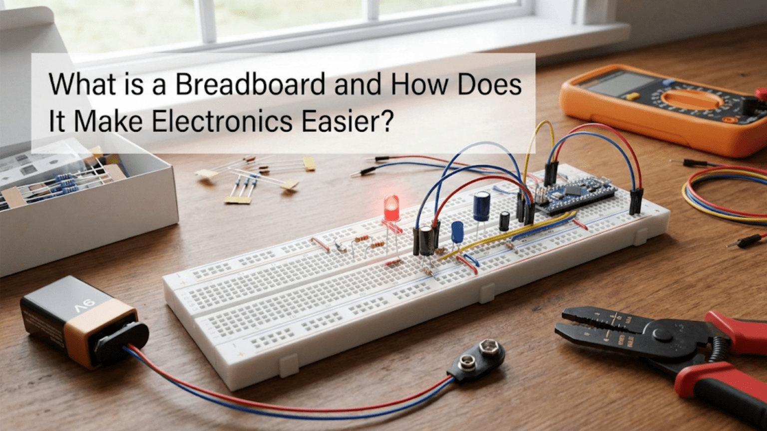
A typical breadboard consists of a rectangular plastic base with hundreds or thousands of small holes arranged in orderly rows and columns across its surface. The plastic is usually white, though some breadboards come in other colors, and features embossed numbers along one edge and letters along another edge forming coordinate labels that help reference specific hole positions when following circuit diagrams or documenting designs. The holes are precisely sized to grip component leads and jumper wires firmly without requiring excessive insertion force, with the diameter typically around one millimeter to accommodate standard component lead sizes.
The hole spacing follows a standard grid pattern with holes separated by two point five four millimeters—exactly one-tenth of an inch—both horizontally and vertically. This standardized spacing, inherited from older electronics construction methods and maintained for compatibility with component lead spacing standards, ensures that integrated circuits, resistors, capacitors, and other components with standard lead spacing insert naturally into breadboards without bending leads or forcing components at awkward angles. The grid regularity also means that distances between any two holes can be easily calculated by counting grid squares, simplifying mental visualization of circuit layouts.
Breadboards come in various sizes from tiny mini-breadboards with perhaps one hundred seventy holes suitable for very simple circuits through standard half-size and full-size breadboards with eight hundred thirty or seventeen hundred holes respectively, to large breadboards combining multiple standard-size sections. Larger breadboards enable more complex circuits or multiple separate circuits on one platform, while smaller breadboards suit simple projects or portable experimentation where compact size matters more than hole count. The modular nature of breadboards allows multiple smaller ones to be placed side by side when more space is needed, providing flexibility in workspace configuration.
The Central Gap and Terminal Strips
The most visually distinctive feature of standard breadboards is the central gap running the length of the board and dividing it into two separate sections. This gap is precisely sized to accommodate dual in-line package integrated circuits, commonly called DIPs or DIP chips, allowing the IC to straddle the gap with pins on each side inserting into holes on opposite sides of the gap. Without this gap, inserting an IC would short all its pins together because both rows of pins would connect to the same terminal strip, preventing the IC from functioning. The gap ensures that the two rows of IC pins connect to separate groups of holes, enabling proper circuit connections to individual IC pins.
On each side of the central gap lie the main circuit building areas called terminal strips. These are the rows of holes where most components insert, with each row containing multiple holes connected together internally but isolated from adjacent rows. The typical pattern has five holes in each connected row, with rows oriented perpendicular to the breadboard’s long axis. Multiple rows align parallel to each other separated by small gaps in the plastic, creating the characteristic striped appearance when viewed from the side. Each five-hole row forms an independent node or connection point, with components inserted in different holes of the same row being electrically connected while components in different rows remain isolated unless deliberately connected with jumper wires.
The numbering along the edges typically labels the rows from one through thirty or sixty or more depending on breadboard size, while the letter labeling indicates columns that group related rows. These labels help document circuits by allowing references like “connect resistor from row 12 column A to row 15 column C,” though many informal breadboard circuits ignore formal labeling and simply describe connections visually or functionally. Professional circuit documentation might reference breadboard coordinates, but beginners can largely ignore the labels while learning unless following instructions that reference them explicitly.
Power Rails: The Side Strips
Along the long edges of most breadboards run continuous strips of holes called power rails or bus strips, distinguished from the main terminal strips by running parallel to the breadboard’s long axis rather than perpendicular to it. These rails typically come in pairs marked with plus and minus symbols or colored red and blue, with one pair along each long edge providing two independent power distribution channels. The holes in each rail connect together along the entire length of the breadboard, creating long continuous conductors ideal for distributing power and ground connections throughout a circuit.
The power rail naming reflects their typical use supplying power to circuits, with the positive rail connected to the positive battery or power supply terminal and the negative rail connected to ground or the negative terminal. Components needing power simply connect to the nearby power rail rather than running long wires back to the battery, dramatically simplifying wiring by providing local access to power and ground anywhere on the breadboard. Similarly, when multiple components share ground connections, they all connect to the ground rail rather than needing dedicated wires to a common point, reducing wire clutter and simplifying physical layout.
Some breadboards feature power rails on both sides with the same-symbol rails on opposite sides connected together internally, while others keep opposite-side rails independent. This difference affects how power distributes across the breadboard, with connected rails providing power access from either side while independent rails enable different power supplies or voltages on opposite sides. Understanding whether your specific breadboard connects opposite rails or keeps them separate prevents confusion when power unexpectedly appears or fails to appear at expected locations. Testing continuity with a multimeter between same-symbol rails on opposite sides quickly clarifies whether they connect or remain independent.
How Internal Connections Work: The Hidden Metal Strips
Understanding the metal contacts hidden beneath the breadboard’s plastic surface reveals why certain holes connect electrically while others remain isolated, enabling correct circuit construction and avoiding mysterious connection problems.
Spring-Loaded Contact Strips
Beneath each row of holes in the terminal strips lies a metal spring clip, typically made from phosphor bronze or similar spring metal alloy, that grips component leads inserted into any hole in that row. The metal clip runs the length of the row connecting all five holes together electrically while remaining isolated from clips serving adjacent rows. When a component lead or wire pushes into a hole, it spreads the spring clip slightly and makes firm electrical contact with the metal, establishing connection to any other leads inserted in the same row. The spring tension holds leads firmly, preventing them from falling out while still allowing removal with moderate pulling force.
These spring contacts can be damaged by inserting leads that are too thick, too rough, or pushed in at angles that force the spring past its elastic limit. Solid wire larger than twenty-two gauge may spread springs excessively, while stranded wire can have individual strands separate and wedge into adjacent rows creating unintended connections. Pushing leads in at steep angles can bend the spring clips permanently, making those holes loose or unreliable. Proper breadboard use requires straight vertical insertion of properly sized leads with smooth gentle pressure, avoiding the temptation to force components or use excessively large wire.
The metal strips for power rails are essentially identical to terminal strip clips but run the entire length of the breadboard rather than just five holes, creating continuous conductors spanning dozens of holes. This difference in strip length distinguishes power rails from terminal strips and determines their different connection patterns—short five-hole strips creating independent nodes in the terminal area versus long strips creating continuous buses in the power rails.
Why Rows Are Grouped in Fives
The five-hole row grouping in terminal strips reflects a balance between providing enough connection points for practical circuit building while maintaining reasonable breadboard size and cost. Five holes per row allows one component lead plus four additional connections—typically sufficient for most simple circuits where components have two leads and might need connections to a couple of other components or wires. The five-hole limit prevents excessive breadboard size while encouraging good practice of using jumper wires to extend connections when more than five total connections are needed at a node.
This grouping becomes particularly relevant when using integrated circuits straddling the central gap. An IC pin inserts in one hole, leaving four additional holes in that row available for connections to that specific pin. For simple ICs requiring just power, ground, and perhaps two or three signal connections per pin, the four available holes typically suffice. More complex situations requiring many connections to one IC pin might need jumper wires linking multiple rows together, expanding the connection capacity beyond the native five holes.
Understanding the five-hole grouping prevents common beginner mistakes like assuming all holes in a column connect together vertically—they do not. Only the five horizontal holes in each row connect, with vertical adjacency meaningless for connectivity. This distinction between horizontal connectivity in the terminal strips and vertical connectivity in the power rails is crucial for correct breadboard usage and a common source of confusion for beginners who might expect vertical columns to connect since horizontal rows connect.
Building Your First Breadboard Circuit
Practical experience building a simple circuit demonstrates breadboard usage and helps internalize the connection patterns and component insertion techniques that make breadboards functional.
A Simple LED Circuit on a Breadboard
The classic first breadboard circuit consists of a battery, resistor, and LED connected in series to create a complete current path. This simple circuit demonstrates all essential breadboard concepts including power distribution through rails, component insertion in terminal strips, and jumper wire use to create connections between separate rows. Starting with a nine-volt battery and using appropriate current-limiting resistor prevents LED damage while providing visible light output confirming the circuit functions.
Begin by connecting the battery to power rails. The nine-volt battery snap has red and black wires that insert directly into breadboard holes, with red connecting to the positive power rail and black to the negative or ground rail. Push the bare wire ends straight down into rail holes until firmly seated, using one hole near the middle of each rail to leave space for other connections on both sides. The power rails now distribute battery voltage along their lengths, accessible from any hole in those rails.
The LED inserts in the terminal strip area, typically with the longer positive lead called the anode positioned in one row and the shorter negative lead called the cathode in an adjacent row. The central gap is unnecessary for this simple circuit, so the LED can go anywhere in the terminal strips with leads in separate rows. Pay attention to LED polarity—the long lead must connect ultimately to positive while the short lead connects to negative for the LED to light. Reversing polarity prevents current flow and the LED remains dark but undamaged.
The current-limiting resistor—typically four hundred seventy ohms to six hundred eighty ohms for a nine-volt circuit—inserts in two additional rows, with one lead in a row shared with the LED cathode and the other lead in a separate empty row. Resistors have no polarity so orientation does not matter, but lead placement creates the series connection essential for current limiting. One resistor lead connects to the LED cathode by virtue of sharing a breadboard row, while the other resistor lead awaits connection to complete the circuit.
Finally, jumper wires create connections from the circuit to the power rails completing the circuit. A wire connects from the row containing the LED anode to the positive power rail, and another wire connects from the row containing the resistor’s free lead to the negative rail. These two connections form a complete series circuit from battery positive through the jumper wire to the LED anode, through the LED to the cathode, into the shared row containing the resistor lead, through the resistor to its other lead, through the second jumper wire back to battery negative through the ground rail.
Verifying Connections and Troubleshooting
After building the circuit, the LED should illuminate indicating successful construction. If the LED remains dark, systematic troubleshooting identifies the problem. First verify battery voltage using a multimeter, confirming the nine-volt battery actually provides voltage and the battery snap connections are secure. Dead or depleted batteries are common culprits in non-functioning circuits.
Next verify breadboard power rail connections by measuring voltage between the positive and negative rails, confirming voltage appears across the rails and the battery wires are inserted securely into the correct rails. If voltage measures correctly at the rails but the LED still does not light, the problem lies in the component connections or component themselves. Check LED polarity ensuring the long lead connects toward positive and the short lead toward negative. Reversed LEDs will not light.
Verify resistor and LED insertion by gently tugging on component leads confirming they are firmly gripped by the breadboard and not merely resting loosely in holes. Check that jumper wires actually insert in the correct rows—a wire intended to connect to the LED anode row but accidentally inserted one row off creates an open circuit preventing current flow. These mechanical connection failures are common breadboard problems easily remedied once identified.
If all connections check correctly but the LED remains dark, either the LED or resistor might be damaged. Substitute a known-good LED or resistor to verify component functionality. Alternatively, measure voltage across the LED with the multimeter—zero volts indicates a short or wrong connection, full battery voltage indicates an open circuit, and approximately two volts indicates the LED is properly forward biased and should be lighting unless the LED itself is defective.
Common Breadboard Mistakes and How to Avoid Them
Understanding typical errors beginners make when using breadboards helps avoid frustration and accelerates the learning process toward confident breadboard usage.
Incorrect Understanding of Connection Patterns
The most common breadboard mistake involves confusion about which holes connect together. Beginners sometimes assume vertical columns connect, leading to circuits where components insert vertically in the same column expecting connection but actually creating open circuits because different rows do not connect vertically. The remedy is always remembering that terminal strip connections run horizontally in rows of five holes, while power rail connections run vertically the full length of the board. Visualizing the hidden metal strips beneath the holes helps internalize this pattern.
Another common error is expecting different rows to connect across the central gap. The gap exists precisely to isolate the two sides, yet beginners sometimes place component leads on opposite sides of the gap in the same row number expecting connection. Row numbers on opposite sides of the gap are completely independent and do not connect despite having identical numbers—the numbering merely provides coordinate reference, not electrical connection. Components bridging the gap must have leads in corresponding positions on opposite sides, but those leads remain isolated until deliberately connected elsewhere in the circuit.
Forgetting that power rails typically run in independent pairs on each side—positive and ground on the left, positive and ground on the right—can cause confusion when circuits built entirely on one side of the breadboard fail to connect to power connected to rails on the opposite side. Unless the breadboard internally connects same-sign rails on opposite sides, explicit jumper wires must distribute power from one side’s rails to the other side’s rails when circuits span both sides. Testing continuity between opposite-side rails clarifies whether jumpers are needed.
Damaged Holes and Poor Connections
Forcing oversized wires or components into holes, inserting leads at angles, or repeatedly inserting and removing components from the same holes can damage the internal spring clips, making those holes loose and unreliable. Symptoms include components falling out easily, intermittent connections that work when components are pressed in firmly but fail when released, or complete lack of connection even with leads fully inserted. Damaged holes should be avoided in future circuit construction, with components placed in nearby undamaged holes instead.
Prevention is better than repair since damaged breadboards are usually not economically repairable. Use appropriate wire sizes—twenty-two to twenty-four gauge solid wire for jumpers, standard component leads sized for breadboard use. Insert leads straight down perpendicular to the board rather than at angles. Avoid excessive insertion and removal cycles from the same holes, spreading circuit construction across different breadboard areas when repeatedly modifying designs. With reasonable care, quality breadboards last through many circuit construction cycles without degradation.
Dirty or oxidized metal contacts can develop over time, particularly in humid environments or with long storage periods. Contacts may appear tarnished or feel rougher than normal, causing higher resistance connections or intermittent contact. Cleaning involves inserting and removing clean wire or component leads repeatedly to scrape oxidation from contacts, though severely oxidized breadboards may need replacement. Storing breadboards in dry conditions with periodic use prevents most oxidation problems.
Component Polarity and Orientation Errors
Components with polarity requirements including LEDs, diodes, electrolytic capacitors, and some integrated circuits must be oriented correctly or they will not function and might be damaged. LEDs have longer positive leads and flat spots on the case indicating negative sides, yet reversed installation is extremely common among beginners who forget to check polarity before insertion. The remedy is developing habits of always checking polarity markings before inserting any polarized component.
Integrated circuits have orientation markings including notches or dots indicating pin one, with pins numbered counter-clockwise from that reference. Inserting ICs rotated one hundred eighty degrees places all pins in wrong positions preventing circuit operation and potentially damaging the IC if power and ground pins reverse. Always verify IC orientation before insertion, referencing datasheets confirming which pins are power, ground, and signals. Mark IC orientation clearly in breadboard layout diagrams to avoid orientation errors during construction.
Transitioning from Breadboards to Permanent Circuits
While breadboards excel for prototyping and learning, finalized designs eventually need transfer to permanent construction methods for reliability and durability in finished projects.
When to Move Beyond Breadboards
Breadboards suit experimentation, learning, and initial prototyping where circuits change frequently and flexibility matters more than robustness. Once a design is finalized and works reliably, transitioning to soldered construction provides connections immune to vibration, accidental disconnection, or degradation from oxidized breadboard contacts. Permanent construction also enables more compact packaging since breadboards are bulky compared to custom PCBs or stripboard construction.
However, breadboards remain valuable even after learning soldering because they enable quick testing of modifications or new circuit sections before committing to permanent construction. Many experienced electronics hobbyists and professionals use breadboards for initial circuit development, moving to permanent construction only after verifying designs work correctly. The rapid iteration breadboards enable during development often saves time compared to soldering and desoldering through multiple design revisions.
Educational and demonstration contexts favor breadboards because observers can see all connections and component placement clearly unlike soldered circuits where the back side of boards hide connection details. Breadboard circuits photograph clearly for documentation and can be modified during demonstrations responding to audience questions or exploring variations. These pedagogical advantages ensure breadboards remain relevant even for people who primarily work with permanent construction methods.
Stripboard and Perfboard Construction
Stripboard, also called Veroboard, consists of a circuit board with parallel copper strips running across it, with holes allowing component leads to insert and solder to the strips. Breaking strips where needed isolates sections, while leaving strips intact provides continuous connections similar to breadboard rows. Circuit layouts transfer from breadboards to stripboard relatively directly since the strip-based connection pattern resembles breadboard rows, though stripboard strips run the full board length rather than grouping in fives.
Perfboard features holes on standard grid spacing but no preconnected strips, requiring wire links soldered between component leads to create connections. This approach provides maximum flexibility since every connection is explicit rather than following predetermined patterns, but requires more soldering work to create connections breadboards provide automatically. Perfboard suits experienced constructors who can visualize connections and efficiently create wiring patterns, while stripboard simplifies construction for designs naturally mapping to strip-based layouts.
Printed Circuit Boards for Final Products
Professional products and sophisticated hobbyist projects eventually use custom printed circuit boards designed specifically for particular circuits, with copper traces connecting components in optimal patterns for electrical performance and physical layout. PCB design software allows translating breadboard prototypes into professional board layouts that manufacturers produce, providing results far superior to stripboard or perfboard in terms of reliability, compactness, and appearance.
The PCB design process requires learning new software and design rules, understanding manufacturing constraints, and investing in prototype board production—complexity justified only for finalized designs that will be built multiple times or for projects where PCB advantages in size, performance, or reliability matter significantly. For one-off projects or purely educational work, breadboards or stripboard often provide adequate results without the additional complexity and cost of custom PCB design and manufacturing.
Conclusion: Breadboards as Essential Learning Tools
Breadboards transform electronics from theoretical knowledge into hands-on practice by enabling quick, easy, reversible circuit construction that encourages experimentation and learning through direct experience rather than fearful hesitation. Understanding how breadboards work—their internal connection patterns linking holes in horizontal rows of five for terminal strips and vertical columns for power rails, their spring-loaded contacts gripping component leads, their central gaps accommodating integrated circuits—removes the mystery and enables confident circuit construction knowing which holes connect and how components should be placed.
The practical value of breadboards for beginners cannot be overstated because they eliminate soldering as a barrier to entry, allowing immediate circuit construction before developing soldering skills. The ability to make mistakes, change designs, and iterate rapidly creates learning opportunities impossible with permanent construction methods where every change requires desoldering and potentially damages components or boards. This freedom to experiment and fail safely accelerates learning and builds confidence through successful circuit construction.
Common mistakes including connection pattern confusion, damaged holes from improper insertion, and polarity errors are easily avoided once understood, with systematic troubleshooting helping identify and fix problems when circuits fail to work initially. The transition from breadboards to permanent construction naturally occurs as skills develop and designs finalize, with breadboards remaining valuable for prototyping even after mastering soldering.
Whether you are just starting electronics or have years of experience, breadboards provide valuable capabilities for circuit development, testing, and demonstration that make them essential tools deserving space in any electronics workshop or learning environment. The time invested understanding breadboard basics pays immediate dividends in enabling hands-on circuit construction that transforms theoretical knowledge into practical skills and working projects.