Introduction: The Transformation Zone
At the heart of every FDM 3D printer sits a component that performs what seems like magic: transforming solid plastic filament into precisely deposited molten material that builds objects layer by layer. This component is the hotend, and while it may appear to be a simple heated nozzle, it’s actually a sophisticated thermal system engineered to accomplish several challenging tasks simultaneously. Understanding what happens inside the hotend demystifies one of the most critical aspects of 3D printing and helps you make better decisions about settings, maintenance, troubleshooting, and even upgrades.
The hotend’s job description sounds straightforward—heat plastic until it melts, then push it through a small opening to deposit it precisely where needed. However, accomplishing this task reliably involves managing competing thermal requirements, controlling material flow with precision, maintaining consistent temperatures under varying conditions, and doing all of this repeatedly for hours or days at a time without failure. The engineering that goes into a well-designed hotend represents decades of refinement and represents one of the key technological achievements that made consumer 3D printing practical.
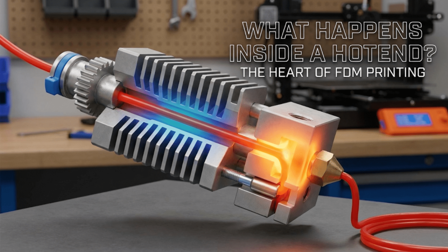
When you watch a 3D printer in action, what you see is the nozzle moving around, leaving behind trails of plastic that gradually build up into recognizable objects. What you don’t see is the complex thermal dance happening inside that small assembly. Plastic enters as a solid, rigid filament, transitions through a carefully controlled melt zone where it becomes viscous and flowable, and exits as a precisely shaped bead that immediately begins cooling and solidifying. All of this happens in a component that might be only forty or fifty millimeters long and twenty millimeters in diameter, yet every millimeter of that length serves a specific purpose.
The challenges the hotend must overcome are more significant than they first appear. Plastic is a poor conductor of heat, yet it must be heated quickly and uniformly. The hotend must be hot enough to melt plastic reliably but can’t be so hot that plastic melts too early, causing jams. Heat must be concentrated in the melt zone and prevented from traveling upward where it would soften filament before it’s ready, causing what’s called heat creep. The molten plastic must flow consistently despite changing back-pressure as the nozzle moves at different speeds and deposits material in varying patterns. Temperature must remain stable even as cooling fans blast air past the hotend to cool the printed part.
Understanding the hotend helps you appreciate why certain print problems occur and how to fix them. When you experience clogs, inconsistent extrusion, stringing, or failed prints, the root cause often lies in how the hotend is functioning or malfunctioning. When you try to print faster, use different materials, or achieve better quality, you’re often bumping up against the limitations of your hotend’s design. This knowledge transforms the hotend from a mysterious black box into a understandable system with predictable behaviors and optimization opportunities.
This article takes you inside the hotend, explaining each component and its function, describing the thermal zones and how they work together, exploring different hotend designs and their trade-offs, and examining how various factors affect hotend performance. Whether you’re a complete beginner trying to understand your printer or an intermediate user looking to troubleshoot issues or consider upgrades, understanding what happens inside the hotend provides insights that improve your 3D printing experience.
The Anatomy of a Hotend: Main Components and Their Roles
A typical FDM hotend consists of several distinct components that work together to create the thermal environment needed for reliable printing. While specific designs vary between manufacturers and models, the fundamental architecture remains consistent across most hotends. Understanding each component and its purpose helps you see how the system functions as a whole and where problems might originate.
The heat break, also called the thermal barrier or throat, is perhaps the most critical component despite its simple appearance. This is typically a tube, often with threaded ends, that serves as the pathway for filament while also creating a thermal barrier between the hot and cold zones of the hotend. The heat break must conduct heat poorly to prevent heat from traveling upward into areas where filament should remain solid, yet it must be mechanically strong enough to withstand the forces of pushing filament through it. This challenging combination of requirements is why heat breaks are often made from stainless steel, which has relatively poor thermal conductivity compared to aluminum or copper but provides adequate strength.
The design of the heat break is crucial to hotend performance. The interior bore must be smooth and precisely sized to allow filament to pass through without excessive friction, yet it can’t be so large that molten plastic flows backward up into it. Some heat breaks feature a thin-walled section in the middle that further reduces heat conduction while maintaining structural integrity. All-metal heat breaks, used in hotends designed for high-temperature materials, must manage heat conduction even more carefully since they don’t include the PTFE liner that some hotends use to reduce friction and provide additional thermal isolation.
The heating block is the mass of metal, typically aluminum, that serves as a heat reservoir and mounting point for heating and sensing elements. This block is directly heated and reaches the target printing temperature. Its thermal mass helps stabilize temperature by resisting rapid temperature changes, though too much mass can make the hotend slow to heat up or respond to temperature adjustments. The heating block includes threaded holes or provisions for mounting the heater cartridge, thermistor or thermocouple, and the nozzle. Some designs include multiple mounting points for nozzles, allowing quick nozzle changes without disassembling the entire hotend.
The heater cartridge is the element that generates heat, converting electrical energy into thermal energy. This is typically a resistive heating element, similar in principle to an electric stove burner but much smaller. Heater cartridges come in different power ratings, commonly ranging from twenty-five to sixty watts for most consumer printers. Higher wattage heaters can heat up faster and maintain temperature better when printing at high speeds that demand rapid material flow, but they also require adequate power supply capacity and proper thermal management. The heater cartridge is pressed or secured into the heating block and must make good thermal contact to transfer heat efficiently.
The thermistor or thermocouple measures temperature and provides feedback to the printer’s control system. Thermistors are the most common temperature sensors, made from materials that change electrical resistance predictably as temperature changes. The printer’s firmware reads this resistance and calculates the current temperature, then adjusts heater power to maintain the target temperature. Accurate temperature measurement is critical for consistent printing, as even small temperature variations can affect material flow and print quality. The thermistor must be secured reliably in the heating block and protected from damage during nozzle changes or maintenance.
The nozzle is the business end of the hotend where molten plastic is forced through a precision orifice to create the extruded bead that forms printed parts. Nozzles thread into the heating block and extend into the heated zone, ensuring plastic remains molten right up to the point of extrusion. The nozzle’s internal geometry includes a conical chamber that funnels plastic toward the small opening and an orifice that determines the width of the extruded filament. Nozzles are replaceable and come in various orifice sizes, typically ranging from zero point two millimeters to one point zero millimeter, with zero point four millimeters being the most common standard size.
The heat sink sits above the heat break and serves the crucial function of actively cooling the upper part of the hotend to prevent heat creep. This is typically an aluminum block with fins to increase surface area, allowing it to dissipate heat more effectively. The heat sink is actively cooled by a fan, called the hotend cooling fan, that runs continuously while the hotend is hot. This cooling ensures that filament remains solid and rigid in the cold zone, maintaining the mechanical properties needed for the extruder to push it reliably through the system. Without adequate heat sink cooling, heat creeps up the heat break, softening filament prematurely and causing jams.
Additional components include the PTFE tube in some hotend designs, which lines the interior of the heat break or extends down into the heating block. PTFE, also known by the brand name Teflon, provides a very low friction surface that helps filament slide smoothly through the hotend. However, PTFE has temperature limitations and begins to degrade above approximately two hundred forty to two hundred fifty degrees Celsius, which is why all-metal hotends without PTFE liners are necessary for high-temperature materials like nylon or polycarbonate. Various mounting hardware, insulation or silicone socks that wrap around the heating block to improve temperature stability and protect against oozing filament, and wiring connecting the heater and thermistor to the control board complete the assembly.
The Cold Zone: Keeping Filament Solid and Pushable
The cold zone, sometimes called the cold end, refers to the upper portion of the hotend where filament must remain solid and maintain its rigidity. This seems counterintuitive at first, after all, isn’t the hotend supposed to be hot? But the cold zone serves the essential function of providing a firm, solid column of filament that the extruder motor can push against. Without a solid section of filament to push, the extruder would simply grind or compress the plastic rather than driving it forward through the melt zone and out the nozzle.
The heat sink is the primary component of the cold zone, and its job is to act as a heat dump, absorbing any heat that conducts upward through the heat break and dissipating it to the surrounding air before it can soften the filament. Heat sinks are designed with fins or other features that maximize surface area, improving their ability to transfer heat to air. The material is typically aluminum because of aluminum’s excellent thermal conductivity and light weight. The heat sink literally pulls heat away from the heat break and releases it to the air.
Active cooling of the heat sink is essential. The hotend cooling fan, which is distinct from the part cooling fan, blows air continuously across the heat sink fins whenever the hotend is at printing temperature. This forced convection dramatically increases heat dissipation compared to passive cooling alone. If this fan fails or becomes obstructed, heat creep rapidly becomes a problem as heat migrates upward faster than the heat sink can passively dissipate it. Many printers monitor this fan and will pause or stop printing if it fails, recognizing that continued printing without heat sink cooling will inevitably lead to jams.
The diameter of the filament path through the cold zone is carefully sized. It must be large enough that filament passes through with minimal friction, preventing excessive force requirements that could cause the extruder to skip steps or grind the filament. However, it can’t be so large that filament has room to buckle or bend, which would prevent effective force transmission. For standard one point seventy-five millimeter filament, the bore through the cold zone is typically around two point zero to two point two millimeters, providing just enough clearance while maintaining guidance. For three millimeter filament systems, dimensions scale proportionally.
The length of the cold zone matters for preventing heat creep. A longer cold zone provides more distance for the temperature gradient to develop between the hot and cold regions, making the heat sink’s job easier. However, a longer cold zone also means a longer flexible filament path, which can cause feeding issues, particularly with flexible materials. Design trade-offs balance these competing requirements, typically settling on cold zone lengths of twenty to forty millimeters depending on the overall hotend design and intended applications.
Some hotend designs include active cooling of the filament itself in the cold zone, beyond just cooling the heat sink. This might involve air gaps around the filament path or even direct contact between the filament and cooled surfaces. The goal is to ensure that filament temperature remains well below the glass transition temperature of the plastic, the point where it begins to soften. For PLA, keeping filament below about fifty degrees Celsius ensures it maintains rigidity. For other materials with different thermal properties, the required cold zone temperature varies accordingly.
The interaction between the cold zone and the extruder is important to understand. The extruder grips filament and pushes it down through the cold zone. The force required depends on the friction in the filament path and the back-pressure from the melt zone and nozzle. If the cold zone becomes partially heat-softened due to inadequate cooling, friction increases dramatically as the softened filament tries to expand and bind against the bore walls. This is one of the most common failure modes, where inadequate heat sink cooling or a failing fan gradually leads to increased resistance until the extruder can no longer push filament, resulting in a jam.
The Transition Zone: Where Solid Becomes Liquid
Between the cold zone where filament is solid and the melt zone where it’s fully liquefied lies the transition zone, a critical region where plastic undergoes its phase change from solid to viscous liquid. This transition doesn’t happen instantly at a single point but rather occurs gradually over a length of filament as temperature increases. Managing this transition zone properly is one of the key challenges in hotend design and operation.
The heat break spans the transition zone, and its thermal properties determine how abrupt or gradual the temperature change is. An ideal heat break would maintain a very sharp temperature gradient, with cold temperatures above and hot temperatures below, minimizing the length of the transition zone. However, real materials conduct heat to varying degrees, and the heat break must balance minimal heat conduction with adequate mechanical strength. Stainless steel heat breaks achieve a reasonable compromise, conducting heat slowly enough to create a useful thermal barrier while providing sufficient strength to withstand the forces involved in printing.
Within the transition zone, plastic softens progressively. Near the top of this zone, plastic maintains most of its rigidity but becomes slightly more flexible and compressible. As you move down and temperature increases, the plastic becomes rubbery, then begins to flow under pressure. Finally, it transitions to a fully molten state where it flows freely. The exact temperatures at which these transitions occur depend on the specific plastic material. PLA, for example, has a glass transition temperature around sixty degrees Celsius where it begins to soften, but doesn’t become fully molten until reaching approximately one hundred eighty to two hundred twenty degrees Celsius.
The length of the transition zone affects several aspects of printing performance. A very short transition zone, achieved through efficient thermal barriers and strong temperature gradients, means less material is in this soft-but-not-molten state at any time. This reduces problems like buckling, where partially softened filament in the transition zone can bend or compress rather than transmitting force effectively. It also reduces the volume of material that must be heated before it’s ready to extrude, allowing faster response to extrusion commands. However, a very sharp transition requires excellent heat break design and aggressive cooling, which may not be practical for all applications.
A longer, more gradual transition zone can sometimes be beneficial, particularly when printing materials that are difficult to melt uniformly or that are sensitive to thermal stress. The gradual heating allows time for heat to penetrate throughout the filament diameter, ensuring that the core of the filament is fully molten rather than just the outer surface. This is particularly relevant for materials with poor thermal conductivity or for larger diameter filaments where the center of the filament strand is far from heat sources.
Heat creep, one of the most common hotend problems, is essentially a failure to properly maintain the transition zone at the intended location. When the heat sink can’t dissipate heat fast enough, either due to inadequate cooling fan performance or excessive heat conduction up the heat break, the transition zone migrates upward. Plastic begins softening in areas where it should remain solid, leading to increased friction, binding, and eventually jamming. The symptoms develop gradually, often beginning with intermittent under-extrusion before progressing to complete blockage.
Retraction, the process of pulling filament back up through the hotend to prevent oozing, interacts critically with the transition zone. When filament retracts, material from the transition zone pulls upward into cooler regions where it may solidify in an expanded state. When printing resumes and this material is pushed back down, the expanded section can create additional resistance or even jam. This is why retraction settings must be carefully tuned, with retraction distance typically kept shorter than the length of the transition zone to avoid pulling molten material into cold areas. The optimal retraction distance varies with hotend design, with all-metal hotends typically requiring shorter retractions than PTFE-lined designs.
Temperature stability in the transition zone depends on the overall thermal system working correctly. The heater, thermistor, control system, and heat sink must all function properly to maintain the intended temperature distribution. Variations in environmental temperature, air flow around the printer, or even differences in printed geometry that affect how heat is being removed by the part cooling fan can influence transition zone behavior. Well-designed hotends are relatively insensitive to these variables, maintaining consistent performance across a range of conditions.
The Melt Zone: Creating Flowable Material
The melt zone, located in and immediately around the heating block, is where plastic reaches full printing temperature and becomes a viscous liquid capable of flowing through the nozzle. This is where the actual melting and flow preparation happens, and the design of this zone significantly affects print speed capabilities, temperature stability, and material compatibility.
The heating block serves as the primary heat source for the melt zone. Its temperature is directly controlled by the heater cartridge and monitored by the thermistor. The thermal mass of the heating block acts as a reservoir of heat energy, helping maintain stable temperature even as heat is being carried away by flowing plastic, conduction through the nozzle and heat break, and convection from air movement. A larger heating block holds more heat energy and resists temperature fluctuations better but takes longer to heat up and cool down. Smaller heating blocks respond more quickly to temperature changes but may struggle to maintain temperature during high-speed printing when material flow is rapid.
Heat transfer from the heating block to the plastic occurs through conduction, with the metal walls of the heat break and nozzle in direct contact with the plastic. The efficiency of this heat transfer depends on the contact area and the thermal conductivity of the materials involved. Brass nozzles, the most common type, conduct heat well and efficiently transfer thermal energy to passing plastic. Stainless steel nozzles conduct heat less efficiently and may require higher set temperatures or slower printing speeds to achieve the same material preparation. The interior surface finish also matters, as rough surfaces can create friction that impedes flow while smooth surfaces promote easy passage of molten material.
The volume of the melt zone determines how much plastic can be in a molten state simultaneously, which affects maximum volumetric flow rate, the ultimate speed limit for printing. A larger melt zone can prepare more material per unit time, enabling faster printing or use of larger nozzles that deposit more material per second. However, a larger melt zone also means more plastic is maintained in a molten state even when not actively printing, which can contribute to oozing or stringing. It also increases the time required for molten plastic to fully purge when switching between materials or colors. Design optimizations seek to maximize melt zone volume enough to support the intended print speeds without creating excessive complications.
Temperature uniformity within the melt zone is important for consistent flow characteristics. If temperature varies significantly across the melt zone, plastic may melt more completely in some regions than others, leading to inconsistent viscosity and flow behavior. The heating block’s thermal conductivity helps even out temperature variations, conducting heat from areas near the heater cartridge to areas farther away. Some advanced hotends incorporate multiple heater cartridges or specially designed heat distribution features to improve temperature uniformity throughout the melt zone.
The viscosity of molten plastic in the melt zone is highly temperature-dependent. Hotter plastic flows more easily, requiring less pressure to push through the nozzle, but may also be more prone to oozing and stringing. Cooler plastic within its printable temperature range flows more sluggishly, requiring higher pressure but generally producing sharper details with less unwanted oozing. The optimal temperature represents a balance between these characteristics and varies by material. The melt zone must maintain whatever temperature the user has selected while minimizing temperature variation during printing.
Plastic enters the melt zone as a solid or partially softened filament from the transition zone and must be heated throughout its cross-section to achieve complete melting. For smaller filament diameters like one point seventy-five millimeters, heat penetrates relatively quickly. For larger diameters like three millimeters, complete melting requires more time and a longer melt zone. This is one reason why smaller diameter filaments have become more popular, they’re easier to melt completely and allow more responsive control over extrusion.
The relationship between melt zone temperature and printing speed involves the concept of residence time, how long each segment of filament remains in the melt zone before being extruded. At slow print speeds, plastic has plenty of residence time to fully melt and reach uniform temperature. At high speeds, residence time decreases, and if speed becomes too high, plastic may not fully melt before being forced through the nozzle, leading to under-extrusion or clogging. This limitation is why high-speed printing often requires high-flow hotends with larger or longer melt zones that can prepare material faster.
The Nozzle: The Final Control Point
The nozzle represents the final stage of the hotend system where molten plastic is shaped and directed onto the print. Despite its small size and seemingly simple appearance, the nozzle’s design and characteristics significantly affect print quality, reliability, and capabilities. Understanding nozzle geometry and function helps you make informed choices about nozzle selection and troubleshooting.
The external geometry of the nozzle is typically conical, tapering from the threaded portion that screws into the heating block down to the tip where the orifice is located. This conical shape serves several purposes. It reduces the nozzle’s mass and thermal inertia, allowing for more responsive temperature control. It minimizes the contact area between the hot nozzle and the printed part, reducing the chance of the nozzle re-melting previously deposited material. The pointed tip allows the nozzle to get into tight spaces and close to previously printed features without collision.
The internal geometry includes a conical chamber that funnels plastic from the roughly two millimeter diameter filament path down toward the much smaller orifice. This tapered chamber gradually reduces the cross-sectional area, building pressure that forces plastic through the small orifice. The angle and length of this taper affect flow characteristics, with steeper angles creating more sudden pressure increases and shallower angles providing more gradual transitions. Most nozzles use an internal cone angle around sixty degrees, providing a good balance between compact size and smooth flow characteristics.
The orifice itself, the tiny opening at the very tip of the nozzle, is precision-machined to a specific diameter. Common sizes include zero point two, zero point four, zero point six, and zero point eight millimeters, though many other sizes are available. The orifice diameter is the primary determinant of extrusion line width, with printed lines typically being one hundred to one hundred fifty percent of the orifice diameter. Smaller orifices allow finer detail and higher resolution but limit maximum flow rate and increase the chance of clogs. Larger orifices enable faster printing and are less prone to clogging but produce coarser detail with more visible layer lines.
The length of the orifice, the straight section at the very tip of the nozzle, also affects performance. A longer orifice provides more guidance and support to the extruded plastic as it exits, helping produce a more consistent bead shape. However, it also increases flow resistance and the chance of clogs. A shorter orifice reduces resistance and is less likely to clog but provides less control over the extruded bead. Most nozzles use an orifice length approximately equal to the orifice diameter, providing a reasonable compromise.
Nozzle material has important implications for performance and longevity. Brass nozzles are the most common due to brass’s excellent thermal conductivity, ease of machining, and relatively low cost. They work well for standard materials like PLA, PETG, and ABS. However, brass is relatively soft and wears quickly when printing abrasive materials like carbon fiber-filled filaments, glow-in-the-dark filaments with phosphorescent particles, or wood-filled filaments. Hardened steel nozzles resist wear much better and are necessary for abrasive materials, but steel’s lower thermal conductivity means they may require slightly higher temperatures or slower speeds for optimal results.
Specialty nozzle materials include stainless steel, which offers good wear resistance with reasonable thermal properties, and exotic options like ruby-tipped nozzles where a synthetic ruby is embedded in the orifice to provide extremely hard, wear-resistant surface while the body remains brass for good thermal characteristics. These high-performance options cost significantly more than brass but can be economical for production environments where nozzle changes would otherwise be frequent.
Nozzle temperature varies slightly from the heating block temperature due to heat loss through the nozzle’s extended tip. This temperature drop is usually only a few degrees but can be more significant with large nozzles, high flow rates, or aggressive part cooling that blasts air near the nozzle. Advanced users sometimes compensate for this by setting nozzle temperature slightly higher than the nominal ideal for their material, though most printers don’t provide separate nozzle temperature measurement, relying on the heating block thermistor as a proxy.
Nozzle maintenance is critical for reliable printing. Over time, charred plastic deposits can build up inside the nozzle, gradually restricting flow and eventually causing clogs. Regular cold pulls or hot pulls, procedures for cleaning the nozzle interior, help maintain flow. External accumulations of plastic from oozing or collisions can be cleaned away with brass brushes or by heating the nozzle and wiping it clean. Eventually, nozzles wear out or become too fouled to clean effectively and require replacement. Having spare nozzles on hand and knowing how to change them is an essential skill for maintaining a 3D printer.
All-Metal Hotends vs PTFE-Lined: Design Trade-offs
Two fundamental approaches to hotend design dominate the consumer 3D printing landscape: all-metal hotends and PTFE-lined hotends. Each design philosophy makes different trade-offs between performance characteristics, temperature capabilities, maintenance requirements, and ease of use. Understanding these differences helps you appreciate your current hotend’s capabilities and make informed decisions about potential upgrades.
PTFE-lined hotends incorporate a PTFE tube that extends from the cold zone down into or through the heating block, sometimes all the way to the nozzle. This tube provides an extremely low-friction path for filament, making it easy for the extruder to push filament through the system. The PTFE lining also provides additional thermal insulation, helping maintain the cold zone’s temperature and reducing heat creep risk. These characteristics make PTFE-lined hotends very forgiving and easy to use, particularly for beginners. They tend to work reliably with minimal adjustment and can print flexible filaments easily because the filament path is fully constrained with minimal friction.
The fundamental limitation of PTFE-lined hotends is temperature. PTFE begins to degrade and release potentially harmful fumes at temperatures above approximately two hundred forty to two hundred sixty degrees Celsius, depending on the specific formulation. This limits PTFE-lined hotends to materials that print at lower temperatures, primarily PLA, PETG, and ABS. High-temperature engineering materials like nylon, polycarbonate, or PEEK that require printing temperatures of two hundred fifty degrees Celsius or higher cannot be safely printed with PTFE-lined hotends. Even ABS, which is sometimes printed at temperatures approaching PTFE’s limits, can be problematic.
Another consideration with PTFE-lined designs is that the PTFE tube itself can be a maintenance item. Over time, particularly when printing near the upper temperature limits, PTFE can degrade or develop deposits that increase friction or cause jams. The PTFE tube may need periodic replacement, typically every few months to a year depending on usage and temperatures. Some PTFE-lined designs, particularly those where PTFE extends into the heating block, can also experience problems with the PTFE deforming under heat and pressure, creating gaps where plastic can accumulate and eventually cause clogs.
All-metal hotends eliminate PTFE from the hot zones, using only metal components throughout the heat break and heating block. This removes the temperature limitation, allowing safe operation at temperatures well above three hundred degrees Celsius if the other components can handle it. All-metal hotends are necessary for printing high-temperature materials and provide more headroom for materials like PETG or ABS that benefit from higher printing temperatures. They also eliminate PTFE as a maintenance item and potential failure point.
The trade-off for all-metal hotends is that they require more precise setup and can be more finicky about settings, particularly retraction. Without the low-friction PTFE lining, filament is in direct contact with metal throughout the heat break, and any slight roughness or misalignment can create friction that causes feeding problems. The risk of heat creep is also higher in all-metal hotends because there’s no PTFE providing thermal insulation. This makes adequate heat sink cooling even more critical. Retraction settings must be carefully tuned because retracting molten plastic into the cooler portions of the all-metal heat break can cause it to solidify in an expanded state, leading to jams.
Some all-metal hotends address these challenges through precision manufacturing and clever design. Highly polished interior bores reduce friction. Optimized heat break designs with thin-walled sections or bi-metal construction minimize heat conduction while maintaining strength. Improved heat sink designs with larger surface areas or more efficient fin geometry enhance cooling performance. These refinements make modern all-metal hotends much more reliable and user-friendly than early designs, though they still generally require more careful setup than PTFE-lined equivalents.
The choice between all-metal and PTFE-lined hotends depends on your material requirements and preferences. If you’re printing exclusively or primarily with common materials like PLA and PETG and want the simplest, most forgiving experience, a PTFE-lined hotend serves well. If you need to print high-temperature materials, want maximum flexibility in material choices, or prefer not to have PTFE as a consumable item, an all-metal hotend is the better choice. Many printers now come with all-metal hotends as standard, reflecting the industry’s movement toward more capable, versatile machines.
Some hybrid designs attempt to get the best of both approaches. These might use PTFE that extends only to the top of the heat break, providing low friction in the cold zone while keeping PTFE away from the highest temperatures. These designs can handle moderately high temperatures, perhaps up to two hundred fifty or two hundred sixty degrees Celsius, while maintaining some of the ease-of-use benefits of PTFE guidance. They represent a middle ground that works well for users who occasionally need higher temperatures but still want some of PTFE’s benefits.
Temperature Control: The PID System at Work
Maintaining precise, stable temperature in the hotend is crucial for consistent print quality, and the system that accomplishes this temperature control is worth understanding. Most 3D printers use PID control, a sophisticated feedback system that continuously adjusts heater power to maintain the target temperature with minimal variation. Understanding how this system works helps you appreciate why temperature stability matters and how to recognize and address temperature-related problems.
PID stands for Proportional, Integral, Derivative, three mathematical terms that describe how the control system responds to temperature errors. An error is the difference between the current temperature measured by the thermistor and the target temperature you’ve set. The control system uses these three different ways of looking at the error to determine how much power to send to the heater cartridge at any given moment.
The Proportional component responds to the current error. If the hotend is ten degrees below target, the heater receives more power than if it were only two degrees below target. This proportional response makes intuitive sense, bigger errors get bigger corrections. However, proportional control alone tends to oscillate, overshooting and undershooting the target temperature repeatedly. The proportional component is necessary but not sufficient for good control.
The Integral component considers the accumulated error over time. If the temperature has been running slightly below target for a while, even if the current error is small, the integral component increases heater power to address this persistent offset. This helps eliminate steady-state errors where proportional control alone would settle at a temperature slightly off target. However, too much integral action can cause overshoot as accumulated error takes time to decrease even after temperature reaches target.
The Derivative component looks at the rate of change of error. If temperature is approaching the target quickly, the derivative component reduces heater power to prevent overshoot. If temperature is falling rapidly, the derivative component increases power to arrest the decline. This predictive aspect of control helps create smoother, more stable behavior by anticipating what will happen based on current trends.
PID tuning involves finding the right balance between these three components for your specific hotend. The optimal values depend on the thermal mass of the heating block, the power of the heater cartridge, the cooling effect of the heat sink fan and any part cooling, and various other factors. Most printers come with reasonable default PID values, but optimal performance requires tuning for your specific setup. Firmware often includes auto-tuning routines that heat the hotend through several cycles, measure its response, and calculate appropriate PID values.
You can observe PID control in action by watching your printer’s temperature graph during heating and printing. A well-tuned PID system shows temperature rising smoothly toward the target, perhaps slightly overshooting by a degree or two, then settling at the target with minimal oscillation. During printing, temperature might vary by one or two degrees as the system responds to changing heat removal rates, but it should remain very close to target. Poorly tuned PID shows larger oscillations, excessive overshoot, or inability to maintain stable temperature during printing.
Temperature stability during printing is challenged by varying heat removal rates. When the printer is depositing material slowly or the part cooling fan is off, less heat is being removed from the hotend and less heater power is needed to maintain temperature. When printing fast with maximum part cooling, heat removal increases dramatically and the heater must work harder. PID control automatically adjusts to these changing conditions, increasing heater power when cooling increases and decreasing power when cooling diminishes.
Some advanced printers include features like look-ahead temperature control, where the control system considers upcoming moves and adjusts temperature in anticipation of changing heat removal rates. This predictive approach can improve temperature stability during rapid changes in print conditions. However, most consumer printers rely on reactive PID control that responds to measured temperature changes rather than predicting them.
Thermistor quality and placement affect control system performance. A thermistor that’s loosely secured in the heating block or has poor thermal contact will show temperature variations that don’t reflect actual heating block temperature, causing the control system to make inappropriate corrections. Securing the thermistor properly and ensuring good thermal contact through thermal paste or proper mechanical pressure is important for accurate control.
Power supply capacity can limit temperature control capabilities. If the power supply can’t deliver sufficient current to the heater cartridge, the system may be unable to maintain target temperature during high-demand situations like fast printing with aggressive part cooling. This manifests as temperature drooping below target during intensive printing despite the PID system commanding full heater power. The solution involves reducing cooling, printing slower, or upgrading to a higher-power heater cartridge if the power supply can support it.
High-Flow and High-Speed Hotends: Performance Upgrades
Standard hotends that come with most printers are designed for reasonable performance across common materials and typical print speeds, representing a balance between capability, cost, and reliability. However, specialized high-flow and high-speed hotends push the boundaries of what’s possible, allowing significantly faster printing or use of larger nozzles for rapid material deposition. Understanding these performance upgrades helps you evaluate whether they’d benefit your printing needs.
The fundamental limitation in standard hotends is volumetric flow rate, measured in cubic millimeters per second. This represents how much molten plastic can flow through the nozzle per second and is the product of print speed, layer height, and extrusion width. A standard hotend might support ten to fifteen cubic millimeters per second reliably. Trying to exceed this limit results in under-extrusion as the hotend simply can’t melt material fast enough to keep up with demanded flow rate. This limits how fast you can print, particularly with thicker layers or larger nozzles.
High-flow hotends increase volumetric flow capacity through several design strategies. The most direct approach is increasing the melt zone volume, providing more space where plastic can be heated. This might involve a larger heating block, a longer heat break passage through the heated zone, or internal geometry that holds more molten plastic. More material in the melt zone means more thermal mass to heat and more plastic ready to flow at any moment, supporting higher flow rates.
Increased heater power is another strategy for high-flow capability. A higher-wattage heater cartridge, perhaps sixty or eighty watts instead of the standard forty watts, can pump more thermal energy into the melt zone per unit time. This allows the hotend to maintain temperature even when rapidly flowing plastic is carrying heat away. The limitation is that the printer’s power supply must be capable of delivering the increased current, and the control system must be able to handle the higher power levels safely.
Some high-flow designs incorporate multiple heater cartridges or longer heater cartridges that distribute heat across a larger volume. This improves temperature uniformity throughout an enlarged melt zone and allows more total heating power. These multi-heater designs require control systems capable of managing multiple heaters, though they might be wired in parallel to appear as a single high-power heater to simpler controllers.
Enhanced heat transfer from heating block to plastic can also improve flow rates. This might involve optimized internal geometries that maximize contact between molten plastic and heated metal surfaces, use of materials with higher thermal conductivity like copper in critical areas, or surface treatments that improve heat transfer. These refinements help the available thermal energy more efficiently reach the plastic that needs heating.
High-speed hotends, often overlapping with high-flow designs, focus specifically on the dynamics of very rapid printing. Beyond just melting plastic quickly, these hotends must handle the mechanical challenges of rapid acceleration, minimize mass to reduce inertia, and maintain temperature stability despite extreme variations in cooling and flow rate. Lightweight construction using materials like titanium for heat breaks reduces moving mass. Compact designs minimize moment of inertia. Advanced cooling management handles the thermal stresses of printing near maximum speed.
Popular high-performance hotends in the consumer market include designs like the E3D Volcano and Super Volcano, which use longer melt zones and larger heating blocks to increase flow capacity. The Mosquito hotend emphasizes lightweight construction and precise thermal management. The Revo system introduces quick-change nozzles that allow swapping nozzle sizes in seconds without tools, making it practical to switch between fine detail nozzles and large high-speed nozzles depending on the print. Each design makes different trade-offs between capability, cost, and ease of use.
The benefits of high-flow hotends are most apparent in specific situations. For large, simple prints where detail is less critical, being able to print at three or four times normal speed can dramatically reduce time investment. For production environments where throughput matters more than pushing absolute detail limits, high-flow capability translates directly to productivity. For prints using large nozzles to quickly deposit material, high flow is essential for taking advantage of those large nozzles.
The trade-offs include increased cost, as performance hotends typically cost several times what standard hotends do. They may also require more sophisticated tuning and maintenance. Some high-flow designs sacrifice fine detail capability, performing best with larger nozzles and thicker layers rather than fine detail work. For users primarily printing detailed models at normal speeds with standard nozzles, a high-flow hotend provides little benefit and may actually be more difficult to work with than a well-designed standard hotend.
Upgrading to a high-flow hotend often requires other system upgrades to realize the benefits. The extruder must be capable of pushing filament fast enough to feed the hotend at high flow rates, requiring powerful motors and reliable filament grip. The motion system must handle higher speeds, requiring adequate acceleration and speed capabilities. The cooling system must keep up with the increased material being deposited. A balanced approach that considers the entire printing system ensures that hotend upgrades translate into actual performance improvements.
Common Hotend Problems and Diagnostic Strategies
Understanding common hotend problems and how to diagnose them is essential for maintaining reliable printing. Many print failures ultimately trace back to hotend issues, and being able to recognize the symptoms and identify the cause helps you solve problems quickly rather than pursuing wrong solutions or accepting poor print quality.
Clogs and jams are the most common hotend problem. They manifest as the extruder motor clicking or skipping as it tries to push filament through a blocked hotend, or as gradually decreasing extrusion until flow stops entirely. Clogs can occur at different locations in the hotend and have different causes. A clog in the cold zone typically results from heat creep, where inadequate cooling allowed plastic to soften where it should remain solid. A clog at the junction between heat break and nozzle might result from a small gap where plastic accumulated over time. A clog in the nozzle itself might be from charred plastic, a small particle of debris, or a partial nozzle blockage from previous printing.
Diagnosing clog location involves systematic elimination. First, remove the filament and try to push new filament through by hand with the hotend at temperature. If filament won’t go through at all, the clog is likely in the nozzle or at the heat break-nozzle junction. If filament goes through but requires excessive force, the issue might be partial blockage or friction in the heat break. If filament goes through easily when cold but jams after the hotend heats up, heat creep is likely the culprit.
Heat creep specifically deserves attention as it’s often misdiagnosed. The symptoms include prints that start fine but gradually develop under-extrusion and eventually jam after a period of time, particularly noticeable on longer prints. The hotend might work perfectly for small quick prints but fail on anything that takes more than an hour. This time-dependent failure mode is characteristic of heat creep, where heat gradually works its way up the heat break over time. The solution involves verifying that the heat sink fan is running properly, ensuring good heat sink contact with the heat break, and potentially improving cooling through upgraded fans or heat sinks.
Temperature fluctuations show up as varying extrusion quality across a print. Areas might look over-extruded while others appear under-extruded despite consistent settings. Watching the temperature graph during printing reveals whether the hotend is maintaining stable temperature. If you see temperature varying by more than a few degrees, investigate PID tuning, thermistor security, thermistor quality, and power supply capacity. Loose thermistors are a common cause, as poor thermal contact causes erratic temperature readings that confuse the control system.
Inconsistent extrusion where flow seems to pulse or vary randomly can result from partial clogs, but can also indicate problems with the extruder motor or filament path rather than the hotend itself. To isolate whether the problem is hotend-related, try extruding into air with the hotend raised off the bed. If extrusion is consistent, the problem may be elsewhere. If extrusion pulses or varies even when extruding freely, the hotend or extruder is involved. Check for partial clogs, verify proper temperature, and ensure the extruder is gripping filament securely.
Stringing and oozing often relate to temperature and retraction settings, both hotend-related. Excessive stringing suggests either temperature is too high, allowing plastic to flow too freely, or retraction isn’t pulling plastic back effectively to prevent oozing during travel moves. Try reducing temperature first, as this often has the biggest impact. If stringing persists, increase retraction distance or speed. If you increase retraction too much and begin experiencing jams, you’ve exceeded what your hotend design can handle and need to back off.
Nozzle wear manifests as gradually increasing print quality problems over time. Fine details become less defined, small features don’t print as intended, and dimensional accuracy degrades. Examining the nozzle tip reveals if the orifice has worn larger or developed irregularities. This is inevitable when printing abrasive materials and is the reason hardened nozzles exist for those applications. For standard materials on brass nozzles, wear develops slowly and nozzles might last for hundreds of hours of printing.
Thermal runaway alarms, where the printer detects that temperature is increasing uncontrollably, typically indicate a failed thermistor, heater cartridge wiring problem, or control system issue rather than a hotend design problem. However, it’s a serious safety issue requiring immediate attention. Never ignore thermal runaway warnings. Verify all wiring connections, check that the thermistor is properly secured and reading reasonable values, and consider whether recent maintenance might have damaged components.
Preventive maintenance reduces hotend problems significantly. Regular cold pulls or hot pulls to clean the nozzle interior prevent accumulation of deposits that gradually restrict flow. Periodically checking and tightening the nozzle prevents gaps from developing. Verifying that the heat sink fan runs properly and that fins aren’t obstructed ensures adequate cooling. These simple maintenance tasks, performed monthly or after every few kilograms of filament, keep hotends operating reliably.
Conclusion: Appreciating the Complexity Within Simplicity
The hotend, for all its small size and seemingly simple function, represents a sophisticated thermal system that makes FDM 3D printing possible. What appears to be a simple heated nozzle is actually a carefully engineered assembly that manages competing thermal requirements, maintains precise temperature control, enables material flow at varying rates, and does all of this reliably across thousands of printing hours. Understanding what happens inside the hotend transforms it from a mysterious component into an understandable system with predictable behaviors and clear maintenance requirements.
The thermal zones—cold zone, transition zone, melt zone, and nozzle—each serve specific functions and must work together seamlessly. Problems in any zone can cascade to affect overall printing performance. The cold zone must remain cool enough to keep filament solid and pushable. The transition zone must remain short and well-defined to prevent issues like heat creep or retraction-related jams. The melt zone must provide adequate heating to fully melt plastic without excessive thermal mass that slows response. The nozzle must shape the molten plastic precisely and withstand the wear and thermal stress of continuous operation.
The evolution from early hotend designs to modern high-performance systems shows how small refinements in understanding and implementation can dramatically improve capabilities. PTFE-lined hotends made early consumer 3D printing practical by providing forgiving operation despite relatively crude thermal management. All-metal hotends enabled high-temperature materials and eliminated PTFE degradation as a limitation. High-flow designs pushed speed boundaries, making production-level throughput achievable on desktop machines. Each generation built on previous knowledge while addressing remaining limitations.
Your relationship with your printer’s hotend should be one of understanding and maintenance rather than mystery and frustration. Knowing what’s happening inside helps you recognize when something isn’t working correctly and narrow down the cause. It helps you set realistic expectations about what your hotend can achieve and when upgrading might be justified. It guides your maintenance efforts toward the most impactful activities that keep your hotend operating reliably.
Temperature control, often taken for granted when it’s working properly, deserves appreciation for its sophistication. The PID system continuously monitors and adjusts to maintain stability despite changing conditions, and proper tuning can make the difference between marginal and excellent printing. Taking time to tune PID values for your specific setup pays dividends in consistency and reliability.
Material capabilities fundamentally depend on hotend design. Understanding whether your hotend is PTFE-lined or all-metal helps you know what materials you can print safely. Recognizing the flow rate limitations of your hotend helps you set realistic speed expectations or guides decisions about nozzle sizes. Knowing your melt zone characteristics helps you understand why certain materials print well while others struggle.
The hotend is not a static component that you install once and forget. It requires periodic maintenance, occasional tuning, and eventual replacement of wear items like nozzles. Developing good maintenance habits and learning to recognize early warning signs of problems prevents minor issues from becoming major failures that waste time and material. The few minutes spent on periodic maintenance save hours of troubleshooting and reprinting.
For those considering hotend upgrades, understanding the capabilities and limitations of different designs helps make informed decisions. High-flow hotends benefit some users tremendously while offering little advantage to others. All-metal conversions enable new materials but require more careful tuning. Quick-change systems improve workflow efficiency if you frequently switch nozzles. Matching hotend capabilities to your actual needs rather than pursuing upgrades because they’re available ensures your investments provide real value.
Looking forward, hotend technology continues to evolve. Manufacturers experiment with new materials, heating methods, and control systems to push performance boundaries further. Understanding the fundamentals discussed in this article provides a foundation for evaluating new developments and understanding what they actually improve versus what’s marketing hype. The core principles of thermal management, material flow, and temperature control remain constant even as specific implementations advance.
The hotend truly is the heart of FDM 3D printing, the component that enables the transformation from solid plastic filament to precisely deposited molten material. Everything else in the printer supports this central function, moving the hotend around, providing filament, cooling the deposited material, and controlling the process. Appreciating what happens inside that small assembly, understanding the engineering challenges it solves, and maintaining it properly ensures that your printer’s heart keeps beating reliably, producing successful prints time after time.