Introduction: The Multidimensional Nature of Print Quality
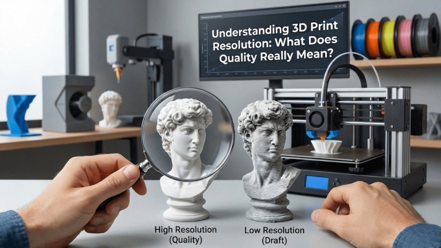
When people first encounter 3D printing, one of the most common questions they ask is “How good is the quality?” This seemingly simple question actually opens up a complex discussion about what quality truly means in the context of additive manufacturing. Unlike traditional photography or display screens where resolution is a straightforward measurement of pixels, 3D printing resolution involves multiple dimensions, different technologies, and various factors that all contribute to what we perceive as quality.
The term “resolution” in 3D printing can be somewhat misleading because it suggests a single number that defines how detailed or accurate your prints will be. In reality, print quality is determined by several independent factors working together, including the vertical resolution controlled by layer height, the horizontal resolution determined by the printer’s mechanical precision and nozzle diameter, the accuracy of positioning systems, the material properties, and even the post-processing techniques you employ. Understanding these different components and how they interact is essential for anyone looking to achieve specific results with their 3D printer.
Many beginners make the mistake of assuming that a printer advertised with “high resolution” will automatically produce perfect parts. They might be disappointed when their prints don’t match their expectations, not realizing that resolution is just one piece of a much larger puzzle. A printer capable of very fine layer heights might still produce poor quality prints if the mechanical components aren’t precise, if the material isn’t appropriate for the application, or if the design itself hasn’t been optimized for 3D printing.
This article takes a deep dive into what resolution really means in the context of 3D printing. We will explore the vertical resolution represented by layer height, examine the horizontal resolution determined by mechanical precision, discuss how these dimensions interact, and understand the practical limitations and trade-offs involved in pursuing higher resolution. By the end, you will have a comprehensive understanding of what to look for when evaluating print quality and how to optimize your own prints for the results you’re trying to achieve.
The Z-Axis: Understanding Vertical Resolution and Layer Height
The most commonly discussed aspect of 3D print resolution is vertical resolution, which refers to how thin each individual layer of material can be. In FDM (Fused Deposition Modeling) printing, the most accessible form of 3D printing for home users and small businesses, this vertical resolution is determined by the layer height setting. Layer height represents the thickness of each horizontal slice of material that the printer deposits, stacked one on top of another to build up the complete three-dimensional object.
Layer height is typically measured in microns (thousandths of a millimeter) or millimeters. Most FDM printers can achieve layer heights ranging from about fifty microns (zero point zero five millimeters) at the finest end to three hundred microns (zero point three millimeters) or even more at the coarsest end. To put this in perspective, a standard sheet of printer paper is roughly one hundred microns thick, so the finest layer heights represent half the thickness of paper, while the coarsest settings are about three times as thick.
The vertical resolution has a dramatic impact on the visible appearance of your prints, particularly on surfaces that aren’t perfectly vertical or horizontal. When you print a curved or angled surface, each layer creates a visible step, similar to how a staircase approximates a slope. These steps are often called “layer lines” and they’re one of the most recognizable characteristics of FDM 3D printed objects. The smaller your layer height, the smaller these steps become, and the smoother the surface appears. A sphere printed at fifty micron layers will look significantly smoother and more refined than the same sphere printed at three hundred micron layers, where the individual layers will be quite visible and give the surface a noticeably ridged texture.
However, layer height isn’t infinitely adjustable. The minimum layer height your printer can achieve is constrained by several factors. The primary limitation comes from the Z-axis stepper motor and the mechanical system it drives. Most printers use lead screws or belts with specific resolutions determined by the motor’s step angle and any gearing or mechanical advantage in the system. A common setup might have a Z-axis resolution of approximately four microns per step, meaning the print head can only move in increments of four microns in the vertical direction. This means you typically want to choose layer heights that are multiples of this fundamental step size. Using layer heights that don’t align with these increments can cause the printer to round to the nearest achievable height, potentially introducing inconsistencies.
The nozzle diameter also plays a crucial role in determining practical layer height ranges. As a general rule, your layer height should be no more than approximately eighty percent of your nozzle diameter, and typically no less than about twenty-five percent. A standard zero point four millimeter nozzle, which is the most common size, works best with layer heights between approximately zero point one millimeters and zero point three millimeters. If you try to use layers that are too thick relative to the nozzle diameter, the extruded plastic won’t be properly compressed against the previous layer, resulting in poor layer adhesion and weak parts. If you try to use layers that are too thin, you may experience under-extrusion problems, clogging, or inconsistent flow because the tiny gap between the nozzle and previous layer restricts material flow.
The relationship between layer height and print strength is another important consideration. Thinner layers generally create more interfaces between layers, and each interface is a potential point of weakness. However, thinner layers also tend to create better layer adhesion because the hot plastic has more surface contact with the previous layer. In practice, the strength difference is often less significant than you might expect, and factors like infill pattern, wall thickness, and material properties typically have a bigger impact on part strength than layer height alone.
One aspect of layer height that beginners often overlook is how it affects the top and bottom surfaces of prints. When you’re printing a flat top surface, having thinner layers means the individual lines of plastic can be placed closer together, creating a smoother, more solid appearance. With thicker layers, the top surface may show more gaps between the lines or require more solid top layers to achieve complete coverage. This is why many printing profiles use different layer heights for the first layer versus the rest of the print, allowing for better bed adhesion with a thicker first layer while maintaining detail in the upper portions.
The XY Plane: Horizontal Resolution and Positioning Precision
While layer height determines vertical resolution, the quality of details in the horizontal plane, often referred to as XY resolution, is equally important for overall print quality. Horizontal resolution is a more complex topic because it’s influenced by multiple factors including the mechanical precision of the printer’s motion system, the diameter of the nozzle, the quality of the stepper motors and their drivers, and even the firmware algorithms controlling movement.
The mechanical precision of your printer’s XY positioning is determined by the resolution of the motion system. In most FDM printers, stepper motors drive belts or lead screws to move the print head and build platform. The smallest movement the printer can make is determined by the motor’s step angle, the pulley or lead screw pitch, and any microstepping capabilities of the motor driver. A typical setup might have a theoretical positioning resolution of twelve point five microns or even finer in the XY plane. This means the printer can theoretically move the nozzle in increments as small as twelve point five microns in the horizontal directions.
However, theoretical positioning resolution and actual achievable detail are not the same thing. Even if your printer can move in very fine increments, several factors limit the actual detail that can be reproduced. The most significant limitation is the nozzle diameter itself. When molten plastic is extruded through a zero point four millimeter nozzle, it comes out as a bead approximately zero point four millimeters wide. No matter how precisely the printer can position the nozzle, it cannot create features significantly smaller than this bead width. The extruded line will always have rounded edges and a certain minimum width determined by the nozzle opening.
Think of it like trying to draw fine details with a marker versus a fine-tip pen. Even if your hand can move with incredible precision, the width of the marker tip limits how fine a line you can draw. Similarly, a zero point four millimeter nozzle simply cannot produce the same level of detail as a zero point two millimeter nozzle, regardless of how precise the printer’s positioning system is. If you need to print very fine details, such as text smaller than a few millimeters, intricate logos, or objects with thin walls, you may need to consider using a smaller nozzle.
Smaller nozzles do come with trade-offs. A zero point two millimeter nozzle can produce approximately twice the detail of a zero point four millimeter nozzle in the XY plane, allowing for much finer features and smoother curves on small objects. However, the smaller opening means less material can be extruded per unit time, significantly increasing print times. A print that takes two hours with a zero point four millimeter nozzle might take six to eight hours with a zero point two millimeter nozzle. Smaller nozzles are also more prone to clogging, require more careful calibration, and may be more sensitive to filament quality issues. Many experienced users keep multiple nozzles on hand and choose the appropriate size based on the specific requirements of each print.
On the opposite end of the spectrum, larger nozzles like zero point six or zero point eight millimeters can dramatically reduce print times for large objects where fine detail isn’t critical. These larger nozzles allow much faster material deposition, making them ideal for functional parts, prototypes, or anything where speed is more important than surface detail. A large vase or functional bracket that might take six hours with a standard nozzle could be completed in two hours with a zero point eight millimeter nozzle and appropriately increased layer heights.
The actual achievable detail in the XY plane is also affected by the printer’s mechanical stability and rigidity. If the printer’s frame flexes during movement, if belts are too loose or too tight, or if there’s play in bearings or linear guides, the actual positioning accuracy will be worse than the theoretical resolution suggests. This is why higher-end printers often feature more rigid frames, better quality linear motion components, and more robust construction even though they may use similar stepper motors and controllers as budget options. The mechanical precision translates directly into the ability to repeatedly position the nozzle exactly where it needs to be, layer after layer.
Motion control algorithms also play a role in horizontal resolution. Modern firmware includes sophisticated features like pressure advance, linear advance, or junction deviation that help control the flow of plastic during acceleration and deceleration. These algorithms can improve the sharpness of corners, reduce artifacts like bulging at direction changes, and generally improve the dimensional accuracy of printed parts. Proper calibration of these features can make a noticeable difference in print quality even on the same hardware.
The Interaction Between Dimensions: How Z and XY Resolution Work Together
Understanding vertical and horizontal resolution separately is important, but recognizing how they interact is crucial for optimizing print quality. The relationship between layer height and XY detail determines the overall appearance and accuracy of your three-dimensional objects, and finding the right balance is often a matter of understanding the specific requirements of what you’re printing.
Consider printing a sphere as a practical example. In the vertical direction, your layer height determines how many layers stack up to form the curved surface. With a zero point one millimeter layer height and a twenty millimeter diameter sphere, you’ll have approximately two hundred layers creating that curve. With a zero point three millimeter layer height, you’ll only have about sixty-seven layers. The difference in visible smoothness will be quite apparent, with the finer layers creating a much more continuous curve and the coarser layers showing pronounced stepping.
At the same time, the horizontal resolution determines how accurately the printer can follow the circular outline at each layer. With a zero point four millimeter nozzle, the printer is essentially approximating the perfect circle with a polygon made up of zero point four millimeter-wide segments. On a small twenty millimeter sphere, this approximation is quite noticeable. The circle won’t be perfectly smooth but will show slight flattening or faceting around its perimeter. With a zero point two millimeter nozzle, this polygonal approximation becomes much closer to a true circle because each segment is smaller relative to the overall curvature.
This interaction explains why different objects benefit from different resolution settings. A tall, thin tower with lots of vertical detail but simple horizontal cross-sections might benefit most from fine layer heights while working perfectly well with a standard or even large nozzle diameter. Conversely, a flat medallion with intricate surface details but minimal height would benefit much more from a smaller nozzle and careful attention to XY resolution while layer height becomes less critical. Many objects, of course, have complexity in all three dimensions and require balancing both aspects of resolution.
The concept of “effective resolution” is useful for understanding this interaction. The effective resolution of a print can be thought of as the smallest feature or finest detail that will be accurately reproduced considering both vertical and horizontal limitations. If you have superb layer height resolution but a large nozzle, your effective resolution is limited by the nozzle. If you have a tiny nozzle but thick layers, the layer height becomes the limiting factor. Optimal print quality comes from matching the resolution capabilities in all dimensions to the requirements of the specific object being printed.
Another important interaction occurs with slanted or angled surfaces. When a surface is neither perfectly vertical nor horizontal but at some angle, both the layer height and XY resolution contribute to how smooth that surface appears. The layer stepping is still present, but the visibility of these steps depends on the angle of the surface. A surface at forty-five degrees shows layer lines differently than a surface at thirty degrees. The step size is determined by the layer height, but the precision with which each layer follows the correct contour depends on the XY resolution. This is why hollow cylindrical objects or cones can be particularly revealing test prints showing both aspects of resolution quality.
The concept of voxels, borrowed from 3D computer graphics, can help visualize this interaction. You can imagine your printed object as being composed of tiny rectangular boxes, or voxels, where each voxel’s dimensions are determined by your XY resolution in two directions and your layer height in the vertical direction. A voxel might measure zero point four millimeters by zero point four millimeters by zero point two millimeters for a typical print with a standard nozzle and fine layers. Your printer can only approximate features larger than these voxel dimensions, and anything smaller will either be lost entirely or distorted by the voxelization process.
Material Flow and Extrusion: The Hidden Factor in Print Quality
While positioning accuracy and nozzle size are often discussed in terms of resolution, the actual flow of material through the system has an equally important impact on the final quality of prints. Even with perfect mechanical positioning and optimal layer heights, inconsistent material flow can create visible defects, dimensional inaccuracies, and surface quality problems that undermine the benefits of high resolution capabilities.
Material flow begins with the filament feeding mechanism. The extruder motor pushes filament into the hotend where it melts and is then forced through the nozzle opening. This seemingly simple process involves numerous variables that affect consistency. The grip of the extruder gear on the filament, the straightness and consistency of the filament diameter, the temperature of the melt zone, the pressure within the nozzle, and the rate at which material is being pushed all interact to determine the actual flow of plastic onto your print.
When you specify a movement speed and extrusion rate in your slicer settings, the printer attempts to coordinate the motion of the print head with the rotation of the extruder motor to deposit exactly the right amount of material exactly where it’s needed. However, this system isn’t perfectly instantaneous. When the printer needs to suddenly deposit more material, such as when starting a new perimeter or filling a wide area, there’s a brief delay as pressure builds up in the nozzle. Similarly, when the flow should stop or slow dramatically, there’s a bit of residual pressure that continues to push out material. These effects create artifacts like slight bulges at the start of perimeters or thin spots immediately after direction changes.
Modern firmware addresses these material flow challenges through various compensation algorithms. Features with names like Linear Advance, Pressure Advance, or Coast settings attempt to anticipate these pressure changes and adjust the extruder motor speed ahead of time to maintain more consistent flow. When properly calibrated, these features can significantly improve dimensional accuracy and surface quality by eliminating or reducing flow-related artifacts. However, they require careful tuning for each combination of material, nozzle size, and printing speed to work optimally.
The extrusion rate also has a maximum limit determined by how quickly the hotend can melt material. This maximum volumetric flow rate, measured in cubic millimeters per second, represents the ultimate speed limit for your printing process. If you try to print too fast with too large a layer height, you’ll exceed this limit and the printer will under-extrude, leaving gaps and weak spots in the print. High-performance hotends designed for fast printing feature longer melt zones and higher power heating elements to increase this maximum flow rate, allowing faster printing speeds without sacrificing quality.
Temperature control precision also affects material flow consistency. If the nozzle temperature varies by even a few degrees, the viscosity of the molten plastic changes, altering how easily it flows and how it bonds to the previous layer. High-quality printers include PID temperature control systems that maintain very stable temperatures, while budget printers might show more temperature fluctuation that can translate into visible inconsistencies in the print surface. You can sometimes see these as subtle variations in shine or texture across a surface, even when the mechanical positioning was perfect.
The interaction between material flow and motion creates some interesting effects on apparent resolution. When a printer moves very quickly and then must make a sharp direction change, the physics of the system can cause slight overshooting or ringing, where the mechanical resonance of the printer continues to vibrate briefly after the intended position is reached. This creates ripples or waves in the print surface that spread out from sharp corners or direction changes. While not technically a resolution issue, these motion artifacts can make prints appear lower quality than their actual positioning accuracy would suggest. Features like input shaping or resonance compensation in firmware work to predict and cancel these mechanical resonances, improving the apparent quality.
Practical Resolution Limits and Real-World Expectations
While printers may advertise impressive resolution specifications, understanding the practical limits of what can actually be achieved helps set realistic expectations and avoid disappointment. The theoretical capabilities of a printer rarely match what you can consistently produce in practice, and knowing where these gaps occur helps you optimize for the results you actually need rather than chasing unattainable perfection.
In terms of layer height, most FDM printers can theoretically achieve layer heights down to twenty-five to fifty microns. However, actually printing at these ultra-fine resolutions presents several challenges. First, the time investment becomes substantial. Since you’re depositing much thinner layers, you need proportionally more layers to reach the same height, and print times can increase by three to five times compared to standard layer heights. A print that takes two hours at two hundred microns might take eight to ten hours at fifty microns.
Second, ultra-fine layers are much more sensitive to any issues with the printer’s Z-axis movement. Any tiny inconsistency in layer positioning, whether from mechanical play, vibration, or binding in the movement system, becomes proportionally more significant when the layers themselves are very thin. What might be an imperceptible variation at two hundred micron layers could cause visible banding or inconsistency at fifty micron layers. This is why achieving good results at very fine layer heights often requires more careful mechanical setup and maintenance.
Third, the benefits of ultra-fine layers diminish beyond a certain point. The human eye has limits to its resolution, and at distances beyond a few centimeters, the difference between fifty micron layers and one hundred micron layers becomes difficult to perceive for most people. Unless you’re creating something that will be examined very closely or photographed in macro detail, investing the extra time for the finest possible layers may not provide noticeable improvement. Many experienced users find that layer heights in the zero point one to zero point two millimeter range provide the best balance of quality and print time for most applications.
For XY resolution, the practical limit is largely determined by nozzle size, as discussed earlier. Even with incredibly precise positioning, a standard zero point four millimeter nozzle cannot reproduce features significantly smaller than about zero point three to zero point four millimeters. Fine details like small text, thin walls, or intricate surface patterns may be lost or merged together. If your design includes features smaller than your nozzle diameter, you have three options: increase the scale of the model, redesign with thicker features appropriate for 3D printing, or switch to a smaller nozzle.
The accuracy with which the printer can match intended dimensions also has practical limits. Even a well-calibrated printer will typically have dimensional accuracy within plus or minus zero point one to zero point two millimeters for most features. This might not sound like much, but it can be significant for parts that need to fit together precisely. If you’re designing mechanical parts with holes for screws or pins, interference fits, or sliding surfaces, you need to account for this typical tolerance in your design. Professional users often print test pieces to measure actual dimensions and adjust their designs accordingly.
Surface finish is another area where expectations should be realistic. FDM printing inherently creates a layered, striated surface that differs fundamentally from smooth injection-molded plastic or machined metal. Post-processing techniques like sanding, filling, painting, or chemical smoothing can improve surface finish significantly, but the as-printed surface will always show some texture from the layer lines and extrusion pattern. If your application requires perfectly smooth surfaces, you’ll need to plan for post-processing or consider alternative manufacturing methods.
One common misconception is that “higher resolution” always means “better quality.” In reality, quality is about matching the capabilities of the printing process to the requirements of the application. A functional bracket printed quickly at three hundred micron layers with a zero point six millimeter nozzle might be perfectly “high quality” for its intended use, even though it lacks the fine surface detail of a miniature sculpture printed at one hundred micron layers with a zero point two millimeter nozzle. Quality is relative to purpose, and understanding this helps you optimize your printing choices for efficiency rather than pursuing unnecessary perfection.
The Role of Model Design in Achievable Resolution
While much discussion about print resolution focuses on printer hardware and settings, the design of the 3D model itself plays a crucial role in what resolution and quality can actually be achieved. A poorly designed model will print badly even on the most precise printer, while a model designed with 3D printing’s capabilities and limitations in mind will look great even on more modest hardware.
The resolution of the digital model file itself is the first consideration. 3D models are typically stored in STL format, which approximates curved surfaces using triangular facets. The number and size of these facets determines how accurately curves and spheres are represented in the file. A model exported with too few facets will have visible flat spots on curved surfaces regardless of how well your printer can reproduce the file. When exporting models from CAD software, you need to ensure adequate facet resolution to capture the curves you want to print. The exact settings vary by software, but generally you want to minimize the size of individual facets while keeping the total file size manageable.
Feature size relative to print resolution is critical. If your model includes features like thin walls, small holes, fine text, or delicate details that are smaller than what your printer can resolve, those features will either be lost entirely or will print in a distorted way that doesn’t match the original design. A vertical wall that’s zero point two millimeters thick in the model will likely not print successfully with a zero point four millimeter nozzle because the nozzle simply cannot fit into that narrow space. Similarly, small holes may close up entirely or print much smaller than intended as the nozzle deposits material around them.
Experienced designers learn to create models with features sized appropriately for their intended printing process. This might mean making walls thicker, enlarging small holes, embossing surface details rather than engraving them, or increasing the size of text. These adjustments ensure that the model’s features are above the minimum threshold that can be successfully resolved by the printing process. Many designers create test prints of critical features to verify that details will come through clearly before committing to printing an entire complex model.
Overhangs and support requirements also affect achievable quality. Features that stick out horizontally without support underneath must be printed with each layer extending slightly beyond the one below it. There’s a practical limit to how far material can bridge without support, typically around forty-five to sixty degrees from vertical depending on material and settings. Beyond this angle, the quality deteriorates rapidly as layers don’t have adequate support and begin to sag or droop. While this isn’t strictly a resolution issue, it affects the quality of the final print significantly. Models designed with gentler angles or with built-in support structures can achieve better quality than models that push these physical limits.
The orientation of a model on the build plate dramatically affects how resolution capabilities translate into final quality. Because layer height is typically coarser than XY resolution, features that run parallel to the build plate will appear smoother than features that must be created by stacking layers. A horizontal cylinder will have a perfectly smooth circular cross-section in the XY plane but may show layer lines along its length, while a vertical cylinder will have smooth sides but may show slight polygonization in its circular cross-section. Choosing the optimal orientation means considering which surfaces are most important for your application and which can tolerate visible layer lines.
Designers can also take advantage of the anisotropic nature of FDM printing by aligning features with the printer’s strengths. Details that will be viewed from above benefit from the XY resolution and can be printed on horizontal surfaces where layer lines won’t be visible. Text and logos often look better when they’re raised from a surface and printed right-side up rather than being recessed or oriented vertically. Thinking about how the printing process will construct each feature helps you arrange things optimally.
Comparing FDM Resolution to Other 3D Printing Technologies
Understanding FDM resolution becomes clearer when compared to other 3D printing technologies. Each approach to additive manufacturing has its own resolution characteristics, strengths, and limitations, and knowing these differences helps you choose the right technology for specific applications.
Resin-based printing technologies like SLA (Stereolithography) and DLP (Digital Light Processing) achieve significantly finer resolution than typical FDM printing. Instead of extruding molten plastic through a nozzle, these technologies cure liquid resin using light, either from a laser or a projector. The XY resolution is determined by the laser spot size or the projector’s pixel size, typically ranging from twenty-five to one hundred microns. Layer heights can be as fine as ten to twenty-five microns, much finer than practical FDM layer heights. This allows resin printers to capture extremely fine details like intricate jewelry patterns, miniature sculptures with delicate features, or dental models with precise anatomical details.
The surface finish of resin-printed parts also differs from FDM. Instead of visible layer lines created by deposited beads of plastic, resin prints show much more subtle layer boundaries and can achieve a smooth, almost injection-molded appearance with minimal post-processing. However, resin printing has its own limitations including smaller build volumes, the need to handle potentially toxic liquid resins, a more involved post-processing workflow involving washing and curing, and generally higher material costs. The technology excels for small, detailed parts but may not be practical for large functional objects.
SLS (Selective Laser Sintering) represents another approach where a laser selectively melts powder material to create each layer. The resolution in SLS is determined by the laser spot size and the particle size of the powder, typically achieving resolutions similar to or slightly better than FDM. The key advantage of SLS is that parts are self-supporting during printing because they’re surrounded by powder, eliminating the need for support structures and allowing more complex geometries. However, SLS equipment is generally much more expensive than FDM or resin printers, and the technology is typically used in industrial settings rather than by hobbyists or small businesses.
Metal 3D printing technologies like DMLS (Direct Metal Laser Sintering) or binder jetting achieve resolutions comparable to plastic SLS but work with metal powders. These technologies can create metal parts with fine features and good surface finish, though the resolution is still measured in tens to hundreds of microns rather than the sub-micron precision of machining. The advantage is the ability to create complex metal geometries that would be impossible to machine, though the equipment cost puts these technologies firmly in the industrial category.
Material jetting technologies spray tiny droplets of material that solidify on contact, similar in concept to inkjet printing but in three dimensions. These systems can achieve very high resolution, particularly in the vertical direction with layer heights as fine as sixteen microns. Material jetting is often used for highly detailed prototypes, master patterns for molding, or applications requiring the highest possible surface finish. Like other high-resolution technologies, material jetting comes with higher equipment and material costs than FDM.
In the context of these comparisons, FDM’s strengths become clear. While it may not achieve the finest resolution or smoothest surface finish, FDM offers the best combination of affordability, material variety, build size, and reliability for many applications. The technology is mature and well-understood, with extensive community knowledge and support. For functional parts, prototypes, tooling, fixtures, and many other applications, FDM’s resolution capabilities are more than adequate. When truly fine detail is needed, the part size is small, and the budget allows, resin printing becomes the better choice. Understanding where each technology excels helps you select the right tool for each job.
Calibration and Testing: Achieving Your Printer’s Best Resolution
Knowing your printer’s theoretical resolution capabilities is one thing, but actually achieving those capabilities consistently requires proper calibration and testing. Even an expensive, high-precision printer will produce poor results if it’s not properly set up and maintained. Fortunately, systematic calibration procedures can help you optimize your printer’s performance.
The foundation of good resolution is proper mechanical setup. This begins with ensuring the printer’s frame is square and rigid with no wobbling or flex. All motion components including belts, linear guides, and lead screws should be properly aligned and adjusted for smooth movement without binding. Belts need appropriate tension – too loose and you’ll get imprecise positioning, too tight and you increase wear and may cause binding. Many printers include belt tensioners that allow adjustment, and learning to recognize proper belt tension by feel or by measuring the resonant frequency of the belt is a useful skill.
Bed leveling is crucial for quality first layers, which set the foundation for everything else. While this might seem unrelated to resolution, an improperly leveled bed means different areas of the first layer will be at different distances from the nozzle. This creates inconsistent extrusion thickness and poor adhesion in some areas, leading to prints that fail or have poor dimensional accuracy at the base. Modern auto-leveling systems help tremendously, but even with auto-leveling, the bed must be roughly level and at the correct distance from the nozzle. Learning to properly calibrate your probe offset and ensure the mesh is accurately representing the bed surface is time well spent.
Dimensional accuracy calibration involves printing test objects and measuring them to verify the printer is producing parts at the correct size. A simple calibration cube, typically twenty millimeters on each side, serves as a basic test. After printing and allowing the part to cool completely, carefully measure each dimension with calipers. If the measurements don’t match the expected twenty millimeters, you may need to adjust the steps per millimeter settings in your firmware to correct for any systematic error in the motion system. This calibration should be done for all three axes independently.
Extrusion calibration ensures the printer is delivering the correct amount of material. This involves measuring a length of filament, commanding the extruder to feed exactly one hundred millimeters of filament, then measuring how much actually moved. If the amount differs from one hundred millimeters, you calculate and input the corrected steps per millimeter for the extruder motor. Proper extrusion calibration prevents over-extrusion, which can cause dimensional inaccuracies and surface blobbing, and under-extrusion, which creates weak parts with gaps between perimeters.
Flow rate calibration refines extrusion further by adjusting for the specific characteristics of each material. Different filament types have different flow characteristics, and even different colors of the same brand can vary slightly. Printing a single-wall cube or tower and measuring the wall thickness helps you dial in the flow rate percentage. The goal is to achieve walls that match your nozzle diameter, indicating the slicer’s assumption about extrusion width matches reality. This seemingly minor adjustment can have significant effects on dimensional accuracy and surface quality.
Temperature calibration involves finding the optimal nozzle and bed temperatures for each material. While manufacturers provide recommended ranges, the ideal temperature for your specific printer and environment may differ. Temperature towers, which print multiple sections at different temperatures, help you identify the temperature that provides the best combination of layer adhesion, surface quality, and dimensional accuracy. Higher temperatures generally improve layer bonding but can cause stringing and oozing, while lower temperatures reduce these issues but may lead to poor adhesion or brittle parts.
Retraction tuning addresses the material flow issues discussed earlier. By adjusting retraction distance and speed, you control how the printer pulls filament back when moving between areas without extruding. Proper retraction prevents stringing and oozing without causing clogs or grinding. Different extruder types, bowden versus direct drive, require different retraction settings, and finding the optimal values for your setup improves print quality significantly.
Linear advance or pressure advance calibration compensates for the lag in pressure buildup and release in the nozzle. This advanced calibration requires printing specific test patterns and visually identifying the setting that produces the most consistent extrusion throughout acceleration and deceleration. When properly tuned, these features can dramatically improve corner sharpness and dimensional accuracy.
Testing actual achievable resolution involves printing specialized test models designed to evaluate different aspects of print quality. Resolution test models include features at various sizes to identify the minimum reliably printable detail. Overhang tests help identify the maximum unsupported angle your printer and material can achieve. Bridging tests determine how far material can span between supports. Dimensional accuracy tests verify that holes, bosses, and other features print at their intended sizes. Running these tests with each new material or after making significant changes to your printer provides concrete data about what you can expect to achieve.
Optimizing Settings for Different Resolution Requirements
Understanding that different objects have different resolution requirements allows you to optimize your print settings for each job rather than always using the same “high quality” preset. This optimization can save significant time while still producing parts that meet their functional or aesthetic requirements.
For functional parts where appearance is secondary to strength and speed, aggressive settings can dramatically reduce print time. Using layer heights of two hundred to three hundred microns with a zero point four or zero point six millimeter nozzle, higher print speeds, and fewer walls or top/bottom layers can complete parts in a fraction of the time required for high-detail settings. The resulting surface will show pronounced layer lines and may have a rough appearance, but if the part will be hidden inside a mechanism, used as a prototype for testing, or simply doesn’t require aesthetic refinement, this approach is perfectly appropriate. Many users maintain separate print profiles labeled “draft” or “fast” for these applications.
For parts requiring good dimensional accuracy but not necessarily smooth surfaces, medium resolution settings provide a good compromise. Layer heights around one hundred fifty to two hundred microns with standard print speeds will produce parts where layer lines are visible but not obtrusive, details are well-defined down to about one millimeter in size, and dimensional accuracy is good. This is often the sweet spot for functional prototypes, tool holders, organizational items, and many hobby projects. Parts print in reasonable time frames while maintaining quality adequate for most purposes.
High-detail settings with layer heights from fifty to one hundred microns, slow print speeds, and multiple perimeters are reserved for situations where surface finish and fine details matter most. This includes display models, miniature figures, parts that will be painted or finished, products that will be photographed, or items where smooth curved surfaces are essential to the design. These settings can triple or quadruple print time compared to draft settings, but the improvement in surface quality and detail resolution justifies the investment when appearance matters.
Vase mode or spiral vase mode represents a special case where you’re printing a hollow object with a single continuous wall. The printer never stops extruding and spirals upward in one continuous motion, creating remarkably smooth surfaces without any layer seams. This mode is ideal for decorative objects, actual vases, light diffusers, or any thin-walled hollow form. Layer heights can be relatively coarse because there’s no horizontal seam between layers, and print times are very fast despite achieving smooth results.
For parts with mixed requirements, where some features need high detail while others don’t, strategic use of variable layer height can optimize the balance. Many slicers allow you to automatically vary the layer height based on the geometry, using finer layers for curved or detailed sections and coarser layers for simple vertical walls. Alternatively, you can manually adjust layer height at specific Z heights. This gives you fine detail where it matters while speeding up sections that don’t require it.
Adaptive layer height takes this concept further by analyzing the model geometry and automatically determining the optimal layer height for each section. Curved surfaces get finer layers to minimize visible stepping, while straight vertical walls get coarser layers since they won’t show layer lines anyway. This can provide quality comparable to fixed fine layers with print times closer to medium settings.
When optimizing for specific materials, resolution settings interact with material properties. Some materials like PLA print reliably at very fine layer heights and slow speeds, making them ideal for high-detail work. Others like ABS or nylon may not perform as well at very fine layers due to their thermal properties and may be better suited to medium or coarse settings. Understanding each material’s sweet spot helps you achieve the best results.
The relationship between speed and resolution deserves emphasis. Printing faster generally reduces quality because the printer has less time to precisely position the nozzle and the material flow becomes more challenging to control. However, the specific speed that causes quality degradation depends on your printer’s capabilities. A rigid, well-tuned printer might maintain excellent quality at speeds that would cause visible artifacts on a less capable machine. Testing your specific setup at various speeds helps identify where quality begins to suffer, allowing you to use the fastest speed that still meets your quality requirements.
Post-Processing and Finishing: Enhancing Apparent Resolution
Even after optimizing printer settings and model design, the as-printed surface of FDM parts will show characteristic layer lines and texture. Post-processing techniques can significantly enhance the apparent resolution and surface quality of printed parts, making them suitable for applications where the raw printed finish wouldn’t be acceptable.
Mechanical post-processing begins with sanding, which can smooth layer lines and create a more refined surface. Starting with coarser sandpaper, around one hundred to one hundred fifty grit, helps remove the most prominent layer lines. Progressing through increasingly fine grits up to six hundred or even twelve hundred grit creates an increasingly smooth surface. The key is patience and avoiding applying too much pressure, which can create gouges or uneven surfaces. Sanding works best on flat or gently curved surfaces and becomes challenging in tight corners or detailed areas.
Filling compounds like automotive spot putty or specialized plastic fillers can fill the gaps between layer lines, creating a smooth surface that sands more easily. After sanding smooth, the filled surface can be primed and painted for a near-perfect finish. This technique is commonly used for props, models, and display pieces where a professional finish is desired. The process is time-intensive but can make FDM prints virtually indistinguishable from other manufacturing methods.
Chemical smoothing uses solvents to partially dissolve the outer surface of the print, causing the plastic to flow and self-level, eliminating layer lines. The most common example is using acetone vapor on ABS prints, where the part is suspended in a sealed container above liquid acetone. The vapor slightly melts the surface, creating a glossy, smooth finish. While effective, chemical smoothing requires careful control to avoid over-softening the part and losing fine details. Different materials require different solvents, and some popular materials like PLA don’t have safe, effective chemical smoothing options.
Priming and painting not only adds color but helps hide surface imperfections. High-build primers designed for filling help cover layer lines, creating a smooth base for color coats. Multiple thin coats of primer, light sanding between coats, and proper surface preparation create professional results. Clear coats can add gloss or matte finishes depending on preference. The painting process can transform a rough-looking print into something that appears professionally manufactured.
Epoxy or resin coating involves applying a thin layer of two-part epoxy or UV resin to the surface. As it cures, the coating self-levels and creates a smooth, often glossy finish. This technique works particularly well for creating waterproof surfaces, adding durability, or achieving a glass-like finish on artistic pieces. The coating can fill small gaps between layers while maintaining fine details that would be lost with heavier fillers.
Heat treatment can improve the surface finish of certain materials through controlled heating that allows the surface to reflow slightly. Using a heat gun at safe distances or placing parts in an oven at carefully controlled temperatures can reduce the prominence of layer lines. This approach requires careful testing to avoid deforming the part, but can create impressively smooth results when done correctly.
Tumbling or vibratory finishing, borrowed from metal working, can smooth parts by subjecting them to hours of gentle abrasion with media in a rotating or vibrating container. This method works well for small parts and creates a uniform matte finish by rounding sharp edges and smoothing surfaces. While not as dramatic as chemical smoothing, tumbling can improve the feel and appearance of functional parts with minimal effort.
The choice of post-processing method depends on the material, the part’s intended use, available tools and materials, and the desired final appearance. Many projects use multiple techniques in combination, such as filling and sanding followed by priming and painting. Understanding these options allows you to start with appropriate print resolution settings knowing you can enhance the results through finishing work.
Common Myths and Misconceptions About Print Resolution
Several persistent myths about 3D print resolution can lead to confusion and poor decision-making. Addressing these misconceptions helps clarify what actually matters for achieving quality results.
Myth one is that “higher resolution always means better prints.” As discussed throughout this article, resolution is just one factor in print quality, and pursuing the finest possible resolution often provides diminishing returns. A print at fifty micron layers isn’t automatically better than one at one hundred micron layers if the increased time and potential for issues outweigh any perceptible improvement in quality. Better prints come from matching resolution to requirements, not maximizing it blindly.
Myth two suggests that “expensive printers automatically produce better quality than budget printers.” While more expensive printers often include features that enable higher quality, such as better mechanical components, automatic bed leveling, or superior motion control, the printer itself is only part of the equation. A budget printer that’s well-assembled, properly calibrated, and used with appropriate settings can produce excellent results, while an expensive printer that’s poorly maintained or misconfigured will disappoint. Operator skill and proper setup matter more than hardware cost for most typical prints.
Myth three claims that “you need a tiny nozzle for good quality.” Standard zero point four millimeter nozzles are perfectly capable of producing high-quality prints for the vast majority of applications. Smaller nozzles are beneficial for specific cases requiring fine details, but they come with significant drawbacks in print time and reliability. Most objects print beautifully with standard nozzles when other factors are properly optimized.
Myth four states that “layer lines are a problem that needs to be eliminated.” Layer lines are an inherent characteristic of FDM printing and aren’t inherently bad. For many functional applications, visible layer lines are perfectly acceptable. The goal isn’t to eliminate layer lines but to control them appropriately for each application. Embracing the aesthetic of 3D printing rather than always trying to hide it is a valid design choice.
Myth five suggests that “all materials print at the same resolution.” Different materials have different optimal settings and capabilities. Some materials can successfully print at very fine layer heights while others work better with thicker layers. Material properties affect how fine details resolve, how smooth surfaces appear, and what finishing options are available. Understanding material-specific capabilities is important for achieving optimal results.
Myth six claims that “resolution only matters for aesthetic parts.” While smooth surfaces and fine details are obviously important for display pieces, resolution affects functional parts too. Dimensional accuracy, which relates to resolution capabilities, determines whether parts fit together correctly. Surface finish affects friction, wear resistance, and suitability for certain environments. Resolution considerations apply across all types of prints, just with different priorities.
Myth seven states that “you can print anything if you just use fine enough settings.” Some geometries and features simply don’t work well with FDM printing regardless of resolution. Features smaller than the minimum printable size will fail, extreme overhangs will sag, and certain materials won’t work for specific applications regardless of settings. Understanding the technology’s fundamental limitations prevents frustration and guides you toward designs that work well within those constraints.
Future Developments in 3D Printing Resolution
The field of 3D printing continues to evolve, and ongoing developments promise to push the boundaries of achievable resolution and quality. Understanding the direction of these improvements helps contextualize current capabilities and anticipate future possibilities.
Hardware improvements focus on increasing mechanical precision and speed simultaneously. Traditional stepper motors are being complemented or replaced by closed-loop systems that provide feedback about actual position, allowing correction of any position errors. Linear rails with higher precision bearings, stiffer frame designs, and better motion control algorithms all contribute to tighter tolerances and more accurate positioning. These improvements help realize the theoretical resolution capabilities that hardware has promised but hasn’t always delivered in practice.
Nozzle and hotend technology continues advancing with designs that allow faster material flow without sacrificing resolution. High-flow nozzles with optimized internal geometry can melt material more efficiently, allowing higher speeds without under-extrusion. Multiple nozzle systems, whether through tool-changing or multiple independent print heads, enable printing with different nozzle sizes in a single print, using a large nozzle for bulk material deposition and a small nozzle for fine details.
Material science plays a crucial role in resolution improvements. New filament formulations with better flow characteristics, more consistent diameters, and enhanced properties enable finer control over the printing process. Materials specifically designed for fine detail work or smooth surface finish help push the boundaries of what FDM can achieve. Composite materials with embedded fibers or particles create new possibilities for functional prints with properties previously unattainable.
Computational advances in slicing software continue improving how digital models translate into physical prints. Machine learning algorithms optimize toolpaths for speed and quality, predict optimal settings based on geometry, and compensate for known printer characteristics. Better simulation of material flow and prediction of artifacts before printing allows preemptive correction. These software improvements can make existing hardware more capable without any physical modifications.
Multi-material and continuous fiber printing technologies are expanding beyond specialty applications into more mainstream use. The ability to combine materials with different properties in a single print, or to embed continuous fibers for reinforcement, creates parts with properties approaching or exceeding traditionally manufactured components. These capabilities change what “resolution” means when you can vary not just geometry but material properties within a single part.
Hybrid manufacturing systems that combine additive and subtractive processes in a single machine offer interesting possibilities. A system might 3D print the bulk of a part quickly with coarse settings, then switch to CNC milling to achieve precise surfaces and tight tolerances on critical features. This combination leverages the strengths of both technologies, using additive manufacturing for complex internal geometries and subtractive processes for precision surfaces.
Artificial intelligence and computer vision are beginning to play roles in real-time quality control. Systems that monitor prints through cameras and adjust settings on-the-fly to maintain quality, detect failures early, or compensate for environmental changes represent a significant advance over the open-loop systems used in most current printers. These smart systems could make high-quality printing more accessible by reducing the expertise required for proper setup and calibration.
The democratization of previously high-end features continues as technologies mature and patents expire. Features once found only on industrial machines gradually make their way into consumer-level equipment. Auto-leveling, which was rare a decade ago, is now standard on even budget printers. Similarly, capabilities like input shaping, pressure advance, and multi-material printing are becoming more widely available at lower price points.
Conclusion: Quality Through Understanding
Understanding print resolution in 3D printing means recognizing that quality emerges from the interplay of multiple factors rather than a single specification. The vertical resolution determined by layer height, the horizontal resolution limited by nozzle size and mechanical precision, the consistency of material flow, the design of the model itself, and the calibration of the printer all contribute to the final result. No single aspect dominates; optimization requires attention to all these elements.
The pursuit of print quality isn’t about maximizing resolution specifications but about understanding what each application requires and matching printer capabilities to those requirements. A functional bracket printed quickly with visible layer lines can be perfect quality for its purpose, while a display model might require fine layers and extensive post-processing to meet its quality requirements. The mark of an experienced 3D printing user isn’t the ability to always print at the finest possible settings, but the wisdom to know when those settings are necessary and when faster, more practical approaches will serve just as well.
Your 3D printer’s resolution capabilities represent potential that can only be realized through proper setup, calibration, and use. A precisely specified printer running with poor calibration will produce worse results than a modest printer that’s been carefully tuned and maintained. The investment of time in understanding your specific equipment, performing systematic calibration, testing different settings, and learning from each print pays dividends in consistently better results regardless of your hardware’s specifications.
As 3D printing technology continues to evolve, the fundamental principles discussed here will remain relevant even as specific capabilities improve. Understanding why certain settings produce certain results, how different factors interact, and what trade-offs exist in any printing decision provides knowledge that transcends any particular printer or technology generation. These principles help you evaluate new equipment, assess the suitability of 3D printing for specific applications, and troubleshoot problems when they arise.
The journey to mastering print resolution and quality is ongoing. Each new material, design, or application presents opportunities to learn and refine your approach. The complexity that initially seems overwhelming becomes second nature with experience, and the ability to look at a design and immediately understand what resolution settings and strategies will produce the best results develops naturally over time. This intuition, built on a foundation of understanding the fundamental principles, represents true mastery of the technology.
Ultimately, 3D printing resolution isn’t about matching some ideal specification but about understanding the relationships between all the factors that contribute to quality and using that understanding to make informed decisions for each unique situation. The question isn’t “what’s the highest resolution I can print at?” but rather “what resolution and settings will produce the result I need most efficiently?” Answering that question differently for each project, based on a deep understanding of the technology’s capabilities and limitations, represents the practical application of everything we’ve explored in this comprehensive examination of print resolution and quality.