Cable management in 3D printers organizes and protects the numerous wires connecting moving components (motors, hotends, heated beds) to the stationary mainboard, preventing wire fatigue, breakage, and interference while ensuring reliable electrical connections throughout the printer’s lifetime. Proper management uses cable chains (drag chains guiding moving wires), strain relief (supporting wires at connection points), secure routing (avoiding pinch points and moving parts), and organized bundling (separating signal wires from power cables), which collectively prevent common failures like broken thermistor wires, intermittent heater connections, and electrical noise affecting print quality.
Introduction
Inside every 3D printer runs a complex web of electrical wiring. Stepper motors need power and control signals. The hotend requires heater power, thermistor connections, and cooling fan wiring. The heated bed demands high-current power cables. Endstops, probes, displays, and other sensors each add more wires. All these connections must reliably carry signals and power from the stationary electronics to components that move constantly—sometimes millions of times over the printer’s life.
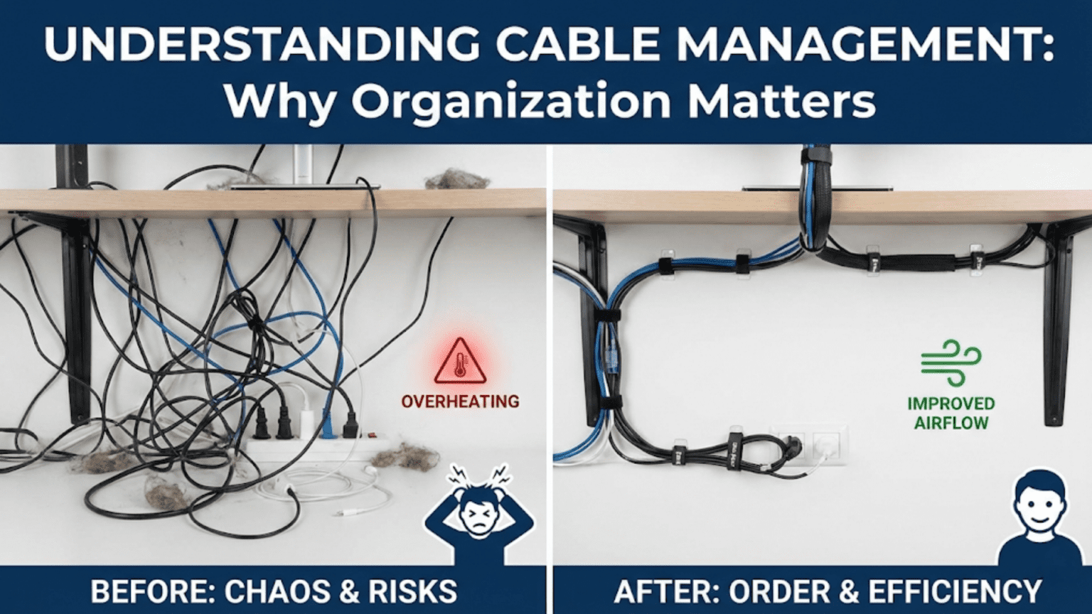
Poor cable management turns this necessary complexity into a reliability nightmare. Wires snag on moving parts. Cables flex repeatedly at poorly supported connection points until they break. Tangled bundles create resistance that motors must overcome. High-current heater wires running alongside sensitive thermistor leads introduce electrical noise. These aren’t hypothetical problems—they’re common failure modes that plague printers with inadequate cable organization.
Yet good cable management often goes unnoticed. Properly routed cables secured with appropriate strain relief, guided through cable chains where needed, and separated by function operate invisibly for years. The printer works reliably, and users never think about the wiring because it simply doesn’t cause problems. This invisible reliability represents cable management done right.
In this comprehensive guide, we’ll explore why cable management matters, examine the tools and techniques for proper organization, understand common failure modes caused by poor wiring, and learn best practices that prevent problems before they occur.
Why Cable Management Matters
Understanding the problems good management prevents:
Preventing Wire Fatigue and Breakage
Flexing Failures:
- Wires aren’t designed for infinite flexing
- Each bend cycle stresses conductors
- Repeated flexing causes work hardening
- Eventually conductors fracture
- Flexible applications need special wire construction
Critical Locations:
- Moving bed connections (Y-axis movement)
- Toolhead connections (X-axis movement)
- Extruder connections (if moving extruder)
- Any connection point to moving components
Failure Progression:
- Thousands of cycles cause microfractures
- Intermittent connection develops
- Full fracture creates open circuit
- Component stops functioning
- Print fails or printer becomes inoperable
Prevention Through Management:
- Strain relief supports wires at connection points
- Cable chains guide movement and control bend radius
- Service loops provide slack for movement
- Proper wire type selection (flexible for moving applications)
Avoiding Pinch Points and Snags
Mechanical Interference:
- Loose cables can catch on moving parts
- Pinched wires create electrical failures
- Snagged cables can stop axis movement
- Crushed insulation causes shorts
Common Hazards:
- Cables crossing linear rail paths
- Wires draped over pulley systems
- Leads hanging into belt paths
- Cables near Z-axis lead screws
- Wiring across movement ranges
Consequences:
- Layer shifts when cable snagged
- Emergency stops from axis binding
- Shorted connections damaging electronics
- Fire hazards from damaged insulation
Reducing Electrical Noise
Signal Integrity:
- High-current cables generate electromagnetic fields
- These fields induce noise in nearby signal wires
- Thermistor readings become erratic
- Endstop signals false trigger
- Communication errors occur
Sources of Interference:
- Stepper motor cables (PWM signals, switching currents)
- Heated bed power (high current, often PWM)
- Hotend heater cables
- Power supply connections
Sensitive Circuits:
- Thermistor wiring (low voltage analog signals)
- Endstop connections
- Probe sensor wiring
- Communication cables (USB, etc.)
Management Solutions:
- Physical separation between power and signal
- Twisted pair wiring for differential signals
- Shielded cables where appropriate
- Grounding strategies
Improving Reliability and Lifespan
Long-Term Operation:
- Good management extends component life
- Reduces maintenance frequency
- Prevents random failures
- Improves overall printer reliability
User Experience:
- Fewer print failures from electrical issues
- Less troubleshooting time
- Confidence in printer reliability
- Professional appearance and operation
Cable Management Tools and Techniques
Cable Chains (Drag Chains)
The standard solution for managing moving cables:
Design and Function:
- Articulated plastic links forming a flexible chain
- Cables run inside the chain
- Chain guides cables through movement
- Controls bend radius to safe limits
- Prevents cables from tangling or dragging
Types:
- Open type: Side panels removable for easy cable insertion
- Closed type: Fully enclosed, better protection
- Semi-open: Slots for ventilation while protecting cables
Sizing:
- Internal dimensions must fit all cables
- Typical sizes: 10×10mm, 10×15mm, 15×20mm, etc.
- Allow 20-30% extra space for airflow and easy installation
- Length matches axis travel plus extra for mounting curves
Installation:
- Fixed end anchors to stationary frame
- Moving end attaches to moving component (bed, carriage)
- Should form gentle curve in middle position
- Avoid excessive tension or slack
Applications:
- Heated bed cables (Y-axis movement)
- Toolhead cables (X-axis movement)
- Any frequently flexing cable bundles
Benefits:
- Dramatically extends cable life
- Prevents tangling and snagging
- Professional appearance
- Predictable, controlled movement
Strain Relief
Supporting cables at connection points:
Purpose:
- Prevents stress concentration at connections
- Transfers mechanical loads to cable body, not joints
- Reduces flexing at vulnerable solder joints or crimps
- Essential for reliability
Methods:
Cable Glands/Grommets:
- Rubber or plastic fittings
- Grip cable jacket
- Distribute stress over length
- Common in industrial connectors
Zip Tie Anchoring:
- Simple but effective
- Secure cable to structure near connection
- Leave small service loop
- Don’t overtighten (damage insulation)
Hot Glue:
- Provides support and stress relief
- Fills gaps and prevents movement
- Useful for delicate connections
- Can be removed if needed (heat gun)
Heatshrink Tubing:
- Reinforces connection area
- Provides mechanical support
- Improves appearance
- Prevents contamination
Commercial Connectors:
- Many include integrated strain relief
- Follow manufacturer installation guidance
- Verify strain relief engages jacket, not conductors
Wire Routing Best Practices
Path Planning:
- Shortest practical route
- Avoid crossing movement paths
- Stay clear of heat sources
- Accessible for maintenance
Separation Strategy:
- Power cables separate from signal
- Minimum 25-50mm spacing where parallel
- Cross at 90° angles if crossing necessary
- Shield or twist signal pairs
Service Loops:
- Extra length at connection points
- Allows movement without tension
- Provides slack for maintenance
- Prevents straight-line pulls on connections
Securing Methods:
- Zip ties at regular intervals
- Adhesive cable clips
- Spiral wrap or expandable sleeving
- Cable combs for parallel runs
Avoid:
- Sharp bends (damage conductors)
- Tight bundling (heat buildup, inflexibility)
- Exposed loops (snagging hazards)
- Crossing hot surfaces
Bundling and Organization
Grouping Strategies:
- Group by function (motor cables together, sensor cables together)
- Separate by voltage level
- Keep high-current paths short and direct
- Signal cables can take longer, cleaner routes
Bundling Materials:
Spiral Wrap: Expandable plastic spiral, easy to apply, allows branching
Expandable Braided Sleeving: Professional appearance, good protection, harder to modify
Cable Ties/Zip Ties: Simple, effective, adjust spacing appropriately
Velcro Straps: Reusable, adjustable, easier for modifications
Labeling:
- Label both ends of cables
- Note function and destination
- Use heat-shrink label tubes or tags
- Invaluable for troubleshooting
Cable Types and Selection
Choosing appropriate wire for applications:
Flexible vs. Standard Wire
Standard Wire (solid or stranded):
- Fine for stationary connections
- Lower cost
- Adequate for most internal wiring
- Not suitable for frequently flexing applications
Flexible Wire (extra-fine stranding):
- Many very thin strands
- Handles repeated flexing
- More expensive
- Essential for moving applications
- Silicone insulation common (flexible, heat resistant)
Application Guide:
- Stationary connections: Standard wire acceptable
- Occasional flex: Quality stranded wire
- Frequent flex (bed, toolhead): Flexible wire required
- High-flex (continuous motion): Specialized flex cable
Shielded Cable
When to Use:
- Thermistor and analog sensor connections
- Long signal cable runs
- Noisy electrical environments
- Communication cables (USB extensions, etc.)
Proper Grounding:
- Shield must ground to be effective
- Ground at one end only (prevent ground loops)
- Usually ground at electronics end
- Verify grounding connection quality
Wire Gauge Considerations
Current Capacity:
- Inadequate gauge = voltage drop and heating
- Heated bed often requires 14-18 AWG
- Hotend heater typically 18-22 AWG
- Motors and signals 22-26 AWG
Length Factor:
- Longer runs need heavier gauge
- Voltage drop increases with length
- Calculate for maximum current at full length
Common Cable Management Problems
Broken Thermistor Wires
Most Common Failure:
- Very thin, fragile wires
- Constant flexing at hotend
- Poor or absent strain relief
- Breaks typically at connection point
Symptoms:
- MAXTEMP or MINTEMP errors
- Erratic temperature readings
- Cannot heat hotend
- Random temperature spikes
Prevention:
- Strain relief at hotend connection
- Service loop before first movement
- Protect wires in sleeve or sheath
- Quality connections (solder, not just crimp)
- Regular inspection
Intermittent Heater Connections
Failure Mode:
- High-current connections subject to heating
- Thermal cycling causes expansion/contraction
- Connections loosen over time
- Broken strands from flexing
Symptoms:
- Inconsistent heating
- Thermal runaway errors
- Temperature doesn’t reach target
- Sparking or burning smell (severe cases)
Prevention:
- Proper wire gauge for current
- Quality connectors with strain relief
- Screw terminal connections verified tight
- Periodic inspection and maintenance
- Solder in addition to crimps for critical connections
Cable Snagging and Layer Shifts
Mechanical Interference:
- Loose cable crosses movement path
- Printer tries to move through cable
- Motor skips steps or axis stalls
- Layer shift or print failure
Common Locations:
- Bed cables hanging too low
- Toolhead cables crossing X-axis path
- Loose sensor wiring
Prevention:
- Secure all cables along entire length
- Test full range of motion before printing
- Cable chains for moving axes
- Regular visual inspection
Electrical Noise Issues
Symptoms:
- Temperature fluctuations
- Endstop false triggers
- Display artifacts
- Communication errors
Causes:
- Signal wires running parallel to power
- Inadequate shielding
- Ground loops
- Poor wire routing
Solutions:
- Physical separation of signal and power
- Shielded cable with proper grounding
- Twisted pair for differential signals
- Shorter signal cable runs
- Ferrite beads on noisy cables
Cable Management Best Practices
For Moving Beds (Y-Axis)
Challenges:
- Large heated bed draws high current
- Constant back-and-forth movement
- Long wire run from electronics
- Significant flexing
Solutions:
- Cable chain absolutely recommended
- Heavy gauge for bed heater (14-16 AWG common)
- Strain relief at both bed and electronics
- Service loop at bed connection
- Separate power and thermistor routing
For Toolhead (X-Axis and Extruder)
Challenges:
- Many cables in small space (heater, thermistor, fans, motor, probe)
- Constant movement
- Heat from hotend
- Limited routing space
Solutions:
- Bundle all toolhead cables together
- Cable chain from frame to carriage
- High-temperature resistant sleeving near hotend
- Strain relief at all connections
- Service loop at toolhead
- Separate thermistor from power cables in bundle
For Z-Axis
Less Critical:
- Limited movement (vertical only)
- Usually slower movement
- Less frequent than X/Y
- Often stationary motor (moving bed or gantry)
Simple Approach:
- Basic bundling and routing adequate
- Strain relief at connections
- Avoid interference with Z-movement
- Keep cables clear of lead screws
Electronics Enclosure
Organization Inside:
- Bundle and route systematically
- Label everything
- Strain relief at enclosure entry
- Separate high and low voltage
- Adequate space for cooling
- Professional appearance aids troubleshooting
Cable Management Comparison Table
| Technique | Cost | Difficulty | Effectiveness | Best For |
|---|---|---|---|---|
| Cable Chain | $$-$$$ | Moderate | Excellent | Moving beds/toolheads |
| Strain Relief (zip tie) | $ | Easy | Good | All connections |
| Strain Relief (proper) | $$ | Moderate | Excellent | Critical connections |
| Bundling (spiral wrap) | $ | Easy | Moderate | General organization |
| Bundling (braided sleeve) | $$ | Moderate | Good | Professional appearance |
| Shielded Cable | $$ | Moderate | Excellent | Signal integrity |
| Proper Wire Gauge | $ | Easy | Essential | Current-carrying |
| Cable Labels | $ | Easy | Very Good | Maintenance/troubleshooting |
Upgrading Cable Management
Improving existing printer wiring:
Assessment
Identify Problems:
- Inspect all connections for damage
- Check for inadequate strain relief
- Look for cables crossing movement paths
- Note inadequate wire gauges
- Identify signal/power proximity issues
Prioritize:
- Safety issues first (fire hazards)
- Reliability problems (frequent failures)
- Quality improvements (noise reduction)
- Aesthetic upgrades last
Systematic Improvement
Step-by-Step:
- Document current wiring (photos, notes)
- Disconnect and remove old wiring section
- Install improved routing/hardware
- Run new or rerouted cables
- Test thoroughly before next section
- Label and document changes
Incremental Approach:
- Don’t redo everything at once
- Test each change before proceeding
- Easier to diagnose if problems occur
- Less overwhelming than complete rewire
Common Upgrades
Adding Cable Chains:
- Biggest single reliability improvement
- Measure travel plus mounting curves
- Size for current cables plus expansion
- Install with gentle middle curve
Replacing Inadequate Wire:
- Heated bed often undersized
- Upgrade to proper gauge
- Use flexible silicone wire for moving applications
- Higher quality connectors
Implementing Strain Relief:
- Add to all moving connections
- Particularly critical for thermistors
- Use appropriate method for each location
- Verify mechanical support, not just aesthetics
Maintenance and Inspection
Regular Checks (Monthly):
- Visual inspection of all visible wiring
- Look for fraying, damage, loosening
- Verify strain relief still secure
- Check zip ties haven’t cut into insulation
Detailed Inspection (Quarterly):
- Flex cables gently, feel for internal breaks
- Tug connections gently (shouldn’t move)
- Inspect inside cable chains
- Verify no new interference developed
Preventive Replacement:
- Replace questionable cables proactively
- Thermistor wires most critical
- Heated bed cables if showing wear
- Better to replace than have print failure
Conclusion
Cable management might seem like a tedious detail compared to exciting upgrades like faster hotends or better cooling, but it represents the foundation of reliable 3D printing. Well-managed cables don’t break, don’t cause noise, don’t interfere with movement, and don’t create safety hazards. They simply work, invisibly supporting successful printing through thousands of movement cycles and hundreds of hours of operation.
Understanding why management matters—preventing flexing fatigue, avoiding pinch points, reducing electrical noise, improving reliability—transforms cable organization from aesthetic preference to functional necessity. The tools and techniques exist to manage any printer’s wiring effectively: cable chains controlling moving cables, strain relief supporting connections, proper routing avoiding interference, and systematic bundling organizing the complexity.
Common problems like broken thermistor wires, intermittent heater connections, and layer shifts from snagging all trace back to inadequate cable management. These failures aren’t inevitable—they’re preventable through proper installation and maintenance. The time invested in good cable management pays dividends in reduced troubleshooting, fewer failed prints, and confidence that electrical problems won’t sabotage your work.
The next time you open your printer’s electronics enclosure or watch the toolhead traverse the build area, look at the cables making it all possible. Those organized, properly supported, systematically routed wires aren’t just tidier than tangled alternatives—they’re more reliable, longer-lasting, and less likely to cause the failures that interrupt your printing. Good cable management might be invisible when done right, but its absence becomes painfully obvious through the problems it would have prevented.