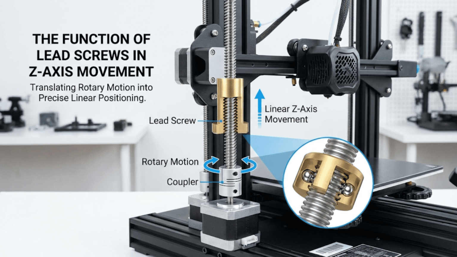
Lead screws convert the rotational motion of stepper motors into precise linear Z-axis movement by using a threaded rod (the lead screw) engaging with a matching nut, where each full motor revolution advances the nut and attached bed or gantry by a specific distance called the lead — typically 2mm, 4mm, or 8mm per revolution depending on the screw’s pitch and thread starts. The lead screw’s mechanical advantage makes it self-locking (the Z-axis holds position without motor power), provides the fine positional control needed for layer height accuracy, and its lead value directly determines the stepper motor steps-per-millimeter configuration required for correct Z-axis calibration.
Introduction
Among all the motion systems in a 3D printer, the Z-axis presents unique challenges. Unlike the X and Y axes—which move quickly back and forth, prioritizing speed—the Z-axis advances in precise, tiny increments with each completed layer. Layer heights of 0.1mm to 0.3mm demand exceptional positional accuracy. The Z-axis must also hold its position without drifting when the motor isn’t actively driving it—otherwise gravity would lower the gantry or bed between layers.
Lead screws elegantly solve all these challenges. The helical threads convert motor rotation into linear movement with a mechanical advantage that provides both fine resolution and self-locking behavior. A single motor revolution advances the Z-axis by only a few millimeters, allowing the stepper motor’s discrete steps to translate into very small linear increments. The thread geometry creates enough friction that the axis holds position without continuous motor power—an essential characteristic that rod-and-belt systems can’t easily achieve.
Understanding lead screws—how they work, why pitch and lead values matter, what makes anti-backlash nuts important, and how to maintain these components—demystifies a critical aspect of printer precision. Z-wobble artifacts, layer height inconsistencies, and calibration difficulties often trace back to lead screw issues. Knowing the system equips you to diagnose and resolve these problems.
In this comprehensive guide, we’ll explore lead screws from fundamental mechanics through practical maintenance, understanding every aspect of this essential Z-axis motion component.
How Lead Screws Work
The basic mechanical principles:
Screw Thread Mechanics
Converting Rotation to Linear Motion:
- Threaded rod (lead screw) rotates
- Matching nut remains fixed to moving component
- Thread engagement converts rotation to translation
- Nut travels along screw as it rotates
The Inclined Plane Principle:
- Thread wraps around cylinder like inclined plane
- Rotation moves nut along the “ramp”
- Mechanical advantage multiplies force
- Small rotational force creates large linear force
- Enables lifting heavy loads with modest motors
Self-Locking Behavior:
- Thread friction prevents back-driving
- Nut cannot push screw to rotate
- Z-axis holds position without motor power
- Unlike belts which would let axis drift
- Critical for maintaining layer height between print layers
Key Lead Screw Terminology
Pitch:
- Distance between adjacent thread crests
- Measured in mm per thread
- Standard metric thread pitches: 1mm, 1.5mm, 2mm
Lead:
- Distance the nut travels per full screw revolution
- Determined by pitch × number of thread starts
- Single-start: lead = pitch
- Multi-start: lead = pitch × starts
Thread Starts:
- Number of independent helical threads
- Single-start: one thread, slower advancement
- 2-start: two threads, 2× faster advancement
- 4-start: four threads, 4× faster advancement
Why Multi-Start Matters:
- More starts = more travel per revolution
- Allows faster Z movement with same motor RPM
- Critical for print speed optimization
- Affects steps-per-mm configuration
Standard Lead Screw Types in 3D Printers
T8 Lead Screws
The near-universal standard for consumer printers:
Naming Convention:
- T8 = trapezoidal thread, 8mm diameter
- Most common variant in 3D printing
- Available in multiple lead configurations
T8 Lead Variants:
- T8×2: 2mm pitch, 1 start = 2mm lead per revolution
- T8×4: 2mm pitch, 2 starts = 4mm lead per revolution (most common)
- T8×8: 2mm pitch, 4 starts = 8mm lead per revolution
T8×4 Dominance:
- 4mm lead per revolution extremely common
- Good balance of speed and resolution
- Standard in most consumer printers
- Well-understood and documented
Steps Per Revolution and Resolution:
- Stepper motor: 200 steps per revolution (1.8° step angle)
- With 16 microstepping: 3200 microsteps per revolution
- T8×4: 3200 microsteps ÷ 4mm = 800 microsteps/mm
- Minimum theoretical step: 1/800mm = 0.00125mm
- Practical resolution: 0.01-0.05mm layer height minimum
T12 Lead Screws
Larger Diameter:
- 12mm diameter shaft
- Greater rigidity
- Better for larger printers
- Less common than T8
- Used when T8 deflects under load
ACME Thread Profile
Trapezoidal Profile:
- 29° or 30° thread flank angle
- Wider thread root for strength
- Designed for power transmission
- Better suited than V-threads for this application
V-Thread Comparison:
- V-threads (metric standard) designed for fastening
- ACME/trapezoidal designed for power transmission
- Trapezoidal handles axial loads better
- Less wedging action reduces wear
Ball Screws (Premium Option)
Different Operating Principle:
- Ball bearings recirculate between screw and nut
- Rolling contact instead of sliding
- Much lower friction
- Higher precision
Advantages:
- Near-zero backlash possible
- Higher efficiency
- Less wear
- Precise positioning
Disadvantages:
- Expensive ($30-100+ vs $5-15 for T8)
- NOT self-locking (requires motor power or brake to hold position)
- Overkill for most 3D printing
- More maintenance
3D Printing Relevance:
- Rare in consumer printers
- Some high-end professional machines
- Self-locking requirement makes lead screws preferred
- Unless motor-on parking implemented
Lead Screw Nuts
The nut is as important as the screw:
Standard Brass Nuts
Material:
- Brass alloy (copper-zinc)
- Softer than steel screw
- Sacrificial wear (nut wears, not screw)
- Self-lubricating properties
Design:
- Simple flange nut
- Screws directly to carriage/bed mount
- No backlash compensation
- Adequate for basic applications
Limitations:
- Backlash from thread clearance
- Wear increases backlash over time
- No compensation mechanism
- Acceptable but not optimal
Anti-Backlash Nuts
What Is Backlash:
- Small gap between screw thread and nut thread
- Necessary for operation (can’t have zero clearance)
- Creates “play” in motion direction changes
- Z-axis: means slight lost motion when reversing direction
Why Z-Axis Backlash Matters:
- When Z reverses direction (unusual but occurs)
- Affects consistency of layer spacing
- Can cause Z-banding artifacts
- More significant on printers with frequent Z direction changes
Anti-Backlash Nut Design:
- Two-piece nut with spring or preload mechanism
- Spring pushes nut halves to engage opposite thread faces
- Eliminates clearance in both directions
- Maintains contact without excessive friction
Types:
- Spring-loaded: Spring pushes nut halves apart
- Delrin/POM nuts: Slightly elastic material grips screw
- Dual-nut: Two separate nuts with preload between them
Benefits:
- Eliminates backlash
- More consistent layer heights
- Reduces Z-banding potential
- Worth the modest cost premium
POM/Delrin Nuts
Material Properties:
- Acetal copolymer
- Slightly elastic—grips screw threads
- Low friction coefficient
- Self-lubricating
- Good wear resistance
Function:
- Slight elasticity creates interference fit on threads
- Eliminates backlash without spring mechanism
- Simple single-piece design
- Quiet operation
Advantages:
- Simple and inexpensive
- Very low friction
- Good backlash elimination
- No springs to fail
Disadvantages:
- Wear faster than metal
- Eventually lose preload (need replacement)
- Temperature sensitivity
- Not for high-temperature applications
Z-Axis Drive Configurations
Different ways lead screws connect to motors:
Direct Motor Coupling
Configuration:
- Lead screw connects directly to motor shaft
- Flexible coupling joins them
- Most common in consumer printers
- Simple and compact
Flexible Coupling:
- Accommodates slight misalignment
- Transmits torque reliably
- Absorbs minor vibrations
- Critical for Z-wobble prevention
Rigid Coupling:
- No flex—requires perfect alignment
- Can transmit motor vibration to screw
- Creates Z-wobble if misaligned
- Generally avoid for lead screws
Dual Lead Screws
Synchronized Z:
- Two lead screws for single Z-axis
- Common in bed-slinger printers
- Provides stability and parallelism
- Requires synchronization
Synchronization Methods:
- Belt-coupled: One motor drives both via belt
- Dual motors: Two motors synchronized by firmware
- Single motor, two screws: Belt from motor shaft to both screws
Tramming:
- Both screws must raise equally
- Ensures bed remains level as Z moves
- Bed tramming adjusts relative heights
- Firmware can compensate with dual motors
Lead Screw Length and Whip
Whip Effect:
- Long unsupported screw deflects during rotation
- Creates vibration and Z-wobble
- Worse at higher rotation speeds
- Critical for tall printers
Mitigation:
- Screw support at top (anti-whip bearing)
- Reduce Z speed
- Screw diameter increase
- Limit maximum Z height
Anti-Whip Bearing:
- Bearing at top of screw constrains deflection
- Doesn’t support thrust load—just radial
- Significantly reduces wobble
- Floating design accommodates thermal expansion
Z-Wobble: Causes and Solutions
The most common lead screw problem:
What Is Z-Wobble
Visual Appearance:
- Wavy or rippled surface on printed parts
- Pattern repeats every revolution of lead screw
- Consistent spacing matches lead (usually 4mm or 8mm)
- Visible on vertical surfaces, especially curved parts
Cause:
- Screw not running true (bent or misaligned)
- Nut rigidly coupled to carriage (no float)
- Wobble transfers to print head position
- Layer deposited at slightly wrong X/Y position
Root Causes
Bent Lead Screw:
- Screws can be slightly bent from manufacturing
- Worse quality screws more often bent
- Creates periodic wobble at rotation frequency
- Roll screw on flat surface to check straightness
Screw Misalignment:
- Screw not perpendicular to bed/frame
- Creates side loads causing deflection
- Rigid coupling amplifies this
- Need alignment during assembly
Rigid Nut Mounting:
- Nut mounted without any float
- Any screw imperfection transfers to carriage
- Prevents screw from running true
- Single biggest contributor to Z-wobble
Solutions
Float the Nut:
- Most effective solution
- Allow nut to move slightly in X/Y
- Decouples screw imperfections from carriage
- Nut can float while still moving Z
- Dramatically reduces Z-wobble
Floating Nut Designs:
- Mount nut to carriage with springs or loose fitting
- Commercial anti-wobble mounts available
- 3D printable solutions widely available
- Allow 1-2mm of float in X/Y plane
Use Flexible Coupling:
- Not rigid coupler between motor and screw
- Jaw coupler, bellows coupler, or similar
- Accommodates alignment differences
- Prevents motor mounting errors transferring to screw
Check Screw Straightness:
- Roll on flat surface, watch for wobble
- Replace bent screws
- Better quality screws are straighter
Proper Alignment:
- Ensure screw perpendicular to frame
- Use squaring tools during assembly
- Reduce side loads on nut
Lead and Steps-Per-Millimeter
The firmware relationship:
Steps/mm Calculation
Formula: Steps/mm = (Motor steps/rev × Microstepping) ÷ Lead (mm)
Example (T8×4, 16× microstepping, 1.8° motor):
- Motor steps: 200 (360° ÷ 1.8°)
- Microstepping: 16
- Total microsteps/rev: 200 × 16 = 3200
- Lead: 4mm
- Steps/mm: 3200 ÷ 4 = 800 steps/mm
Common Values:
- T8×2 (2mm lead): 1600 steps/mm at 16× microstepping
- T8×4 (4mm lead): 800 steps/mm at 16× microstepping
- T8×8 (8mm lead): 400 steps/mm at 16× microstepping
Why Accuracy Matters:
- Wrong steps/mm creates dimensional errors in Z
- All layer heights scaled incorrectly
- Total print height wrong
- Easy to verify and correct
Calibration Verification
Test Method:
- Home Z-axis
- Note current Z position (0)
- Command Z to move specific distance (e.g., 100mm)
- Measure actual movement with calipers
- Compare commanded vs. actual
- Adjust steps/mm proportionally if different
Adjustment:
- New steps/mm = Current steps/mm × (Commanded ÷ Actual)
- Example: Commanded 100mm, actual 98mm
- New = 800 × (100 ÷ 98) = 816 steps/mm
Lead Screw Maintenance
Proper care extends component life:
Lubrication
Why Lead Screws Need Lubrication:
- Sliding contact creates friction and wear
- Dry screws wear faster
- Can create noise and vibration
- Inadequate lubrication causes problems
Recommended Lubricants:
- White lithium grease: Most recommended
- PTFE-based lubricant: Dry, less contamination
- Super Lube: Excellent synthetic grease
- Avoid: WD-40 (too thin, washes away), motor oil
Application:
- Clean screw first (remove old lubricant)
- Apply thin coat to screw threads
- Move Z-axis full range to distribute
- Wipe excess (attracts debris)
Frequency:
- Every 3-6 months typical
- More often in dusty environments
- When movement becomes noisy or rough
- After any major cleaning
Inspection and Cleaning
Regular Checks:
- Visual inspection for contamination
- Listen for unusual sounds (grinding, popping)
- Feel for rough spots during manual movement
- Check nut for play or wear
Cleaning Process:
- Power off printer
- Wipe screw with dry cloth to remove loose debris
- Apply solvent (IPA) to remove old grease
- Allow to dry completely
- Apply fresh lubricant
- Cycle through full range
Replacement Indicators
Lead Screw:
- Visible wear on thread flanks
- Significant corrosion
- Bent or deformed
- Dimensional changes from wear
Nut:
- Significant play when wiggled on screw
- Rough engagement despite lubrication
- Spring failure (anti-backlash type)
- Worn thread faces
Lead Screw Comparison Table
| Screw Type | Lead (mm/rev) | Steps/mm (16× micro) | Speed | Resolution | Cost | Best For |
|---|---|---|---|---|---|---|
| T8×2 (1-start) | 2 | 1600 | Slow | Very High | $ | High precision, slow printers |
| T8×4 (2-start) | 4 | 800 | Moderate | High | $ | Most consumer printers (standard) |
| T8×8 (4-start) | 8 | 400 | Fast | Moderate | $ | Fast Z movement, ABL-heavy |
| T12×4 | 4 | 800 | Moderate | High | $$ | Larger printers, rigidity |
| Ball Screw | Varies | Varies | Very Fast | Very High | $$$ | High-end, precision machines |
Upgrading Lead Screws
When to Upgrade:
- Z-wobble unresolvable with current screw
- Worn nut causing inconsistent layers
- Want faster Z movement (higher lead)
- Building larger printer needing more rigidity
Upgrade Options:
- Better quality T8 (same spec, better straightness)
- Anti-backlash nut upgrade (from standard brass)
- Float mount addition (reduces wobble without changing screw)
- Higher lead screw (faster but less resolution per step)
- T12 for larger/heavier applications
Steps/mm Reconfiguration Required:
- Any lead change requires firmware update
- Recalculate and verify before printing
- Test calibration object after change
Conclusion
Lead screws represent one of the most elegant mechanical solutions in 3D printer design—converting motor rotation into precise Z-axis linear movement through the ancient technology of screw threads, updated with modern materials and precision manufacturing. Their self-locking property addresses the Z-axis’s unique requirement to hold position without continuous power, while their mechanical advantage enables modest motors to lift heavy beds and gantries reliably.
Understanding lead values, pitch, and thread starts reveals why T8×4 has become the standard—providing the right balance of speed and resolution for typical consumer printing applications. Recognizing what anti-backlash nuts accomplish and why floating nut mounts dramatically reduce Z-wobble equips you to troubleshoot common Z-axis problems and implement effective solutions. Knowing the steps-per-millimeter relationship between lead screw geometry and firmware configuration enables accurate calibration.
Proper maintenance—keeping screws clean and lubricated, replacing worn nuts before they cause problems, checking alignment periodically—extends component life and maintains print quality. The Z-axis demands less attention than X and Y (fewer cycles, lower speeds, less dynamic loading), but neglected lead screws eventually create the Z-wobble and layer inconsistency artifacts that undermine an otherwise well-tuned printer.
The next time you hear the soft whir of the Z-axis advancing between layers or watch the bed descend to its home position, appreciate the lead screw making it possible. That threaded rod translating motor steps into precise fractions of a millimeter is the mechanical foundation of your printer’s ability to build objects layer by perfect layer, converting electrical pulses into the physical reality of additive manufacturing.