Introduction: From Box to Beautiful Prints
The journey from receiving your first 3D printer to producing your first successful print involves several critical setup steps that can seem daunting to beginners. While modern printers have become increasingly user-friendly, the initial setup process still requires attention to detail, patience, and systematic approach to ensure everything works correctly from the start. Proper setup creates the foundation for all your future printing success, while rushed or incomplete setup creates problems that may plague you for weeks or months until you discover and correct the initial mistakes.
The setup process varies significantly between different printer models and types. A fully assembled plug-and-play printer might require only minimal setup taking an hour or two, while a kit printer requiring complete assembly could take several hours or even a full day for someone new to the process. However, regardless of your specific printer model, certain universal steps and principles apply to virtually all FDM printers. Understanding these common elements helps you approach setup systematically and gives you confidence even when your printer’s specific instructions are unclear or incomplete.
One crucial mindset for successful setup is recognizing that this is not a race. While you’re naturally eager to start printing, taking time to understand each step, verify everything is correct before moving forward, and not skip steps because they seem optional will save enormous time and frustration later. The hour you spend carefully leveling the bed during setup saves dozens of hours fighting adhesion problems. The thirty minutes you invest in properly assembling and aligning components prevents mysterious print quality issues that would take days to diagnose. Patience during setup is one of the best investments you can make in your 3D printing journey.
Documentation becomes your most valuable resource during setup. Your printer should include assembly instructions, quick start guides, and reference materials either in physical form or available for download. Read through all documentation before starting rather than discovering important information halfway through assembly when you’ve already made mistakes. Many manufacturers also provide video assembly guides that show the process in motion, often clearer than written instructions alone. Taking time to review all available resources before starting assembly prevents most common setup errors.
The physical workspace where you set up your printer matters more than you might initially realize. You need adequate space not just for the printer itself but for moving around it during assembly and maintenance. Good lighting helps you see small components and verify correct assembly. A stable, level surface prevents the printer from rocking or vibrating during operation. Easy access to power outlets, reasonable temperature conditions not too hot or too cold, and protection from dust or excessive airflow all contribute to reliable printing. Considering these environmental factors during initial setup prevents problems that might otherwise not become apparent until after you’ve printed several objects.
Safety considerations deserve attention during setup. You’ll be working with electrical connections, heating elements that reach dangerous temperatures, and moving mechanical parts. Following proper safety practices including verifying power is disconnected when working on electrical connections, being aware of hot surfaces during operation, keeping fingers clear of moving components, and ensuring the printer is stable and won’t tip protects you from injury. 3D printing is generally safe when treated with appropriate respect, but accidents can happen if you’re careless during setup or operation.
This article walks through the complete setup process from unboxing through your first successful print, covering physical assembly if required, electrical connections, software installation, initial calibration, and finally that crucial first print that validates everything works. While we can’t cover every specific printer model’s unique requirements, we’ll focus on the universal steps and principles that apply broadly, with notes about common variations you might encounter. Whether your printer arrives fully assembled or as a box of components, whether it includes automatic bed leveling or requires manual adjustment, and whether it uses SD cards or USB connections, the fundamental setup process follows similar patterns that this guide will help you navigate successfully.
Step 1: Unboxing and Inventory
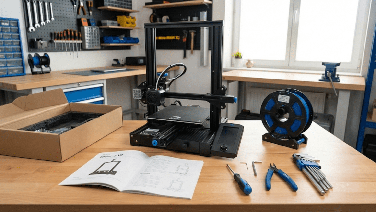
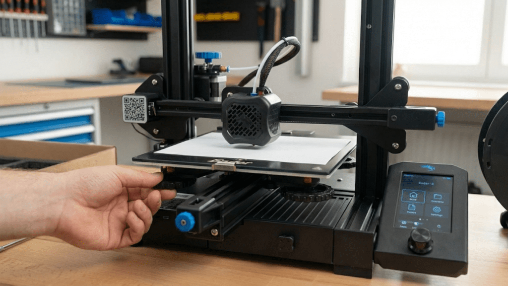
The setup process begins the moment you open the box containing your new printer. Proper unboxing prevents damage, helps you identify all components, and gives you an overview of what you’re working with before diving into assembly.
Start by finding a clean, clear workspace large enough to spread out all components. You’ll need room for the printer itself plus packaging materials, small parts, tools, and documentation. Hardwood floors or tables work better than carpet where small parts might disappear. Good lighting is essential for seeing small components and reading part labels clearly.
Before removing anything, photograph the box contents as they’re packed. Manufacturers typically pack items in protective foam or cardboard inserts designed to prevent damage during shipping. These photos provide reference if you need to repack the printer for any reason or if parts seem to be missing but are actually hidden in packaging. Remove items methodically, setting aside all packaging materials in case you need them.
Locate the inventory list or packing list that should be included with your printer. This document lists every component, part, tool, and accessory that should be present. Systematically verify each item on the list against what you actually received. Lay out small parts in organized groups, screws in one area, brackets in another, electronic components in another. This organization prevents losing pieces and makes them easy to find during assembly.
Check for obvious shipping damage to any components. Examine the printer frame or partially assembled components for dents, cracks, or bent parts. Inspect electronic components for cracked circuit boards or damaged connectors. Check that motors rotate smoothly without binding or grinding. Report any damage to the seller immediately before proceeding with assembly, as assembling damaged components may void your warranty or return options.
Identify all included tools. Many printers include basic tools like Allen keys, screwdrivers, or wrenches needed for assembly. Organize these separately as you’ll need them shortly. If your printer requires tools not included, make a list now so you can gather them before starting assembly. Common tools for printer assembly include metric Allen key sets, adjustable wrenches, wire cutters, and screwdrivers.
Locate all documentation including assembly manuals, quick start guides, and safety information. If physical documentation seems incomplete, check whether the manufacturer provides downloadable manuals on their website. Many companies now provide extensive online documentation including assembly videos that supplement printed guides. Bookmark or download these resources for easy reference during assembly.
Inspect filament if sample filament is included. Many printers include a small spool of PLA to get you started. Check that the filament isn’t tangled and that the end isn’t buried deeply in the spool where you can’t easily find it. Store filament in a sealed bag with desiccant if you’re not using it immediately to prevent moisture absorption.
Examine the build plate or print bed. If it has a protective film or covering, note whether this should be removed before use. Some protective films are temporary for shipping while others like PEI sheets are permanent build surfaces. Documentation should clarify what stays and what goes. Check that the bed surface is clean without obvious scratches or contamination.
Verify power supply components and cables. Ensure the power supply is rated for your region’s voltage and that you have all necessary power cables. Some printers ship with different power supplies for different markets, verify yours is correct. Check power cable insulation for any damage from shipping.
This inventory and inspection process might take fifteen to thirty minutes but it’s time well spent. Discovering missing parts or damage now before assembly prevents frustration later when you’re halfway through the build and discover you can’t continue. Most suppliers are responsive about replacing missing or damaged components if you report issues immediately, but once you’ve assembled the printer your options are more limited.
Step 2: Physical Assembly (If Required)
If your printer arrived fully assembled, you can skip most of this section after removing any shipping restraints or protective packaging. For partially assembled or kit printers, careful assembly creates the foundation for all future performance.
Begin by carefully reading through all assembly instructions before starting any physical work. Understanding the complete process helps you recognize how parts relate to each other and prevents mistakes from misunderstanding instructions. If video guides are available, watch them completely before starting to build mental models of the assembly sequence.
Organize your workspace with all parts easily accessible. Group related components together and keep small parts in containers where they won’t roll away. Stage parts in the order you’ll need them according to the assembly sequence. This organization prevents time wasted hunting for specific parts during assembly.
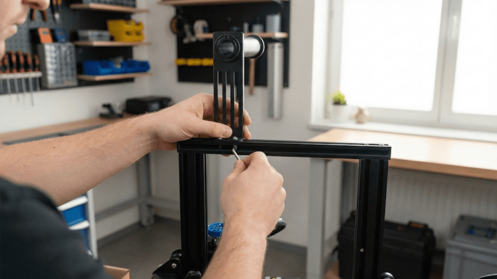
Start with the frame or base assembly, as this provides the foundation everything else attaches to. Frame assembly typically involves connecting vertical members to base members using screws or bolts. Pay careful attention to orientation, many frame components can be installed upside down or backwards but only work correctly one way. Look for identifying marks, labels, or threaded holes that indicate proper orientation.
Tighten frame fasteners progressively rather than fully tightening each one before moving to the next. Initial assembly should have screws snug but not completely tight, allowing slight adjustment. After assembling the complete frame or sub-assembly, check that everything is square and aligned, then progressively tighten all fasteners to final torque. This progressive tightening prevents parts from binding or being forced into incorrect positions by early over-tightening.
Verify frame squareness using measuring tools or by checking diagonal measurements. Rectangular frames should have equal diagonal measurements from corner to corner when properly squared. Small variations can significantly affect print quality by causing motion system misalignment. Take time to get the frame square before final tightening, as adjusting it later is much harder.
Install linear rails, lead screws, or threaded rods that guide motion. These components must be straight and parallel to their corresponding axes. Bent lead screws cause Z-wobble, misaligned rails cause binding, and non-parallel components create uneven motion. Check straightness visually and by rolling rods on a flat surface. Slight bends in lead screws might be acceptable if they rotate smoothly without wobbling, but significant bends warrant requesting replacement components.
Mount motors in their designated positions, ensuring they’re securely attached and oriented correctly. Motor shafts should rotate freely without binding. Motor wiring should route neatly without interfering with moving components. Use zip ties or cable clips to secure wiring as you go, preventing cables from catching on moving parts later.
Install belts that connect motors to moving components. Belt tension is critical, too loose and positioning becomes imprecise, too tight and motors struggle or bearings wear prematurely. Most printers include tensioning mechanisms, use them to achieve proper tension. Correct tension allows belts to twang like bass guitar strings when plucked but not be so tight they’re difficult to depress. Some documentation provides specific tension measurements or tools.
Attach the print head assembly including hotend, fans, and extruder. This is often a pre-assembled component you mount to the X-axis carriage. Verify cooling fans can spin freely without hitting shrouds or wiring. Ensure the nozzle has adequate clearance above the bed at all positions. Check that all print head wiring routes cleanly and won’t catch during motion.
Mount the print bed or build plate. Beds typically attach to a carriage that moves on the Y-axis or Z-axis depending on printer design. Verify the bed sits flat and stable on its mounting points. Check that adjustment screws or springs that allow bed leveling are installed correctly and move smoothly. The bed should be roughly level initially, though precise leveling comes later.
Make all electrical connections following the wiring diagram in your documentation. Most printers use color-coded or labeled connectors that only fit in correct locations, but verify each connection against the diagram rather than assuming. Common connections include motor plugs, thermistor sensors, heating elements, cooling fans, limit switches, and power supply connections. Never force connectors, if they don’t insert easily you probably have them oriented incorrectly or are trying to connect to the wrong port.
Install the control board or electronics, often in a box or housing that protects components from dust and debris. Verify ventilation for electronics cooling is unobstructed. Check that the control board is securely mounted without loose screws that could create shorts if they contact circuit board traces.
Perform a final assembly check before connecting power. Verify all screws are tightened, all connectors are secure, all belts are tensioned, and no loose parts remain. Check that all axes move freely through their full range of motion without binding or interference. Push the print head through its X and Y travel, verify the bed or gantry moves smoothly through Z travel. Any binding or unusual resistance indicates misalignment or interference requiring correction before powering on.
This assembly process varies in duration from one hour for simple partial assembly to six or eight hours for complex full kit builds. Take breaks as needed, assembly fatigue leads to mistakes. If you get stuck, consult documentation, search for assembly videos specific to your printer model, or ask in community forums before forcing anything or guessing at correct procedures.
Step 3: Initial Power-On and Firmware Verification
With physical assembly complete, connecting power and verifying the printer’s firmware responds correctly are crucial steps before attempting any calibration or printing.
Before connecting power, perform a final visual inspection of all electrical connections. Verify no bare wires are exposed, all connectors are fully seated, and no wiring crosses hot components or moving parts. Check that the power supply voltage selector, if present, is set correctly for your region. In countries using one hundred twenty volts, the selector should be on one hundred twenty volts; in countries using two hundred twenty to two hundred forty volts, set it accordingly. Connecting power with incorrect voltage settings can instantly damage the printer.
Connect the power supply to wall power but leave the printer’s power switch in the off position initially. Check the power supply for proper operation, usually indicated by an LED on the power supply. If this light doesn’t come on, verify the wall outlet has power and check any fuses in the power supply. Only proceed once you confirm the power supply is receiving and providing power correctly.
Turn on the printer’s power switch and observe initial startup. The printer should display signs of life including lights, display activation, and possibly fan operation. If nothing happens, verify the power switch is correctly wired and the power supply is connected to the control board. If the display shows error messages, note them for troubleshooting before proceeding.
Navigate the printer’s menu system to become familiar with the interface. Locate critical functions including temperature controls, movement controls, and settings menus. Each printer has unique menu organization but common elements include prepare, control, and information screens. The prepare menu typically includes preheat functions and movement controls. The control menu includes temperature settings, fan controls, and motion parameters. The information menu shows firmware version and printer configuration.
Check firmware version displayed in the information menu. Note this version number, as you may need to reference it when seeking help or determining whether firmware updates are available. Most printers ship with relatively recent firmware, but manufacturers occasionally release updates fixing bugs or adding features. You can update firmware later if desired, but initial setup should use the firmware as shipped unless you encounter specific problems it updates would address.
Test axis motion using manual movement controls. Most printer menus include functions to jog the printer in X, Y, and Z directions by specific distances. Start with small movements, perhaps one or ten millimeters, before attempting large movements. Verify each axis moves in the correct direction when commanded. If X movement produces Y motion or if motion is reversed from expected, this indicates wiring errors requiring correction before proceeding.
Listen for unusual noises during motion testing. Motors should operate relatively quietly with slight whirring sounds. Grinding, clicking, or squealing indicates binding, misalignment, or mechanical interference requiring investigation. Belts should run smoothly without slapping sounds. Fans should spin freely without rattling. Any concerning sounds warrant stopping and identifying their source before continuing setup.
Test temperature sensors by checking displayed temperatures. At room temperature, hotend and bed temperatures should show values close to ambient temperature, typically eighteen to twenty-five degrees Celsius depending on your environment. If temperatures show extreme values like two hundred degrees or negative fifty degrees, thermistor connections are likely incorrect or damaged. Verify thermistor wiring before attempting to heat anything.
Heat the hotend briefly to around one hundred fifty degrees to verify the heating element and thermistor work correctly. Watch the temperature display as heating begins. Temperature should climb smoothly toward the target. If temperature overshoots target by more than five to ten degrees before stabilizing, PID settings may need tuning, though this is usually acceptable initially. If temperature doesn’t climb or shows unstable readings, check heater and thermistor connections.
Heat the bed to around fifty or sixty degrees to verify bed heating functions. This takes longer than hotend heating as beds have more thermal mass. Temperature should climb steadily though more slowly than the hotend. Verify the bed surface feels warm to touch after several minutes of heating, confirming the thermistor measures actual bed temperature rather than showing false values.
Test limit switches or endstops that tell the printer where it is in space. Many printers include homing functions that move each axis until it triggers its limit switch, establishing zero positions. Execute homing carefully, ready to hit the emergency stop if anything seems wrong. Successful homing indicates limit switches work correctly and motors can find reference positions. Failed homing requires troubleshooting switch wiring or positions.
Verify fans operate correctly by turning them on through menu controls. Part cooling fans should be controllable with variable speed. Hotend cooling fans may run continuously or activate automatically when hotend temperature exceeds set values. Check that airflow from each fan is appropriate and in expected directions.
This verification process takes thirty minutes to an hour but ensures all printer systems function before proceeding to calibration and printing. Problems discovered at this stage are usually simple wiring errors easily corrected, while problems discovered after attempting calibration or printing can be confusing to diagnose. Systematic verification of each subsystem creates confidence everything works as designed.
Step 4: Software Installation and Configuration
With the printer physically operational, installing and configuring slicing software lets you prepare files for printing. The software side of setup is as important as hardware assembly for successful printing.
Choose your slicing software based on your printer and personal preferences. Popular options include Cura, PrusaSlicer, and Simplify3D. Many printer manufacturers recommend or provide pre-configured versions of slicing software optimized for their printers. Using manufacturer-recommended software minimizes configuration effort as basic settings are already established for your printer model.
Download the slicing software from the official website or manufacturer’s download page. Avoid downloading from third-party sites that might include modified or compromised versions. Installation procedures vary by operating system but typically involve downloading an installer, running it, and following prompts. Most slicers are free or have free versions with all essential functionality.
Launch the slicing software for the first time and complete initial setup wizards if presented. Many slicers walk new users through selecting their printer model from lists or inputting basic printer specifications manually. If your printer appears in preset lists, selecting it automatically configures appropriate settings including build volume, nozzle size, and firmware type.
If your printer isn’t in preset lists, you’ll manually configure basic parameters. Critical settings include build volume dimensions matching your printer’s actual capacity, nozzle diameter typically zero point four millimeters unless you specifically installed a different size, and firmware flavor typically Marlin for most hobbyist printers. Consult your printer documentation for exact specifications.
Configure connection between computer and printer if you plan to control printing directly rather than using SD cards. Most printers connect via USB cable with some supporting network connections. Install any required drivers for USB communication. Some printers appear as virtual serial ports while others require specific driver software. Test connection by accessing printer control functions in your slicer’s interface, verifying you can send commands to the printer.
However, many users find SD card printing more reliable than direct computer connections, as computer issues, USB communication problems, or screen savers don’t interrupt SD card prints. Configure your printer for SD card use if preferred, ensuring SD cards are properly formatted, typically to FAT32 file system, and that the printer’s SD card slot works correctly.
Configure material profiles in your slicing software. At minimum, configure PLA settings since you’ll likely print PLA for initial testing. Material profiles include temperatures for hotend and bed, cooling settings, and print speeds. If using manufacturer-recommended slicer configurations, material profiles are typically pre-configured appropriately. Review these settings and note their values for future reference.
Familiarize yourself with basic slicing workflow by loading a simple test model. Most slicers include sample models or you can download simple calibration objects from model repositories. Practice loading models, positioning them on the virtual build plate, and generating toolpaths through the slicing process. Export sliced G-code files to locations where you can access them, either saving to computer folders for transfer to SD cards or directly to SD cards.
Configure any printer-specific settings available in your slicer. This might include start G-code that runs before each print, end G-code that runs after prints complete, and custom printer commands for special operations. Many slicers include sensible defaults but verify these settings aren’t obviously incorrect for your printer model.
Set up user interface preferences to match your work style. This includes themes, measurement units, and which settings panels display by default. While these don’t affect print quality, comfortable software environments make learning easier and more pleasant. Spend a few minutes making the interface work for you.
Test the complete workflow by slicing a simple object and generating G-code. Verify the generated file saves correctly and you can access it. If using SD cards, confirm you can transfer files to cards and cards insert and eject cleanly from your printer. If using direct connection, verify you can send files to the printer over USB.
Practice basic model manipulation in your slicer including moving, rotating, and scaling objects. These operations are essential for proper model placement and orientation, discussed in depth in previous articles. Understanding basic manipulation now prevents confusion when positioning actual prints later.
This software setup process typically takes thirty minutes to an hour, longer if troubleshooting connection issues or learning complex software. However, time invested learning your slicer fundamentals pays dividends in all future printing as comfortable software proficiency accelerates your workflow and helps you achieve better results through understanding available options.
Step 5: Bed Leveling and Z-Offset Calibration
Proper bed leveling creates the foundation for first layer adhesion and overall print success. This crucial calibration deserves careful attention as it affects every print you’ll ever make.
Begin by ensuring the bed and hotend are at printing temperature. PLA typically uses bed temperature around sixty degrees and hotend around two hundred to two hundred ten degrees. Heating before leveling accounts for thermal expansion that affects bed geometry and nozzle height. Many materials expand with heat, and leveling cold then printing hot results in incorrect spacing.
If your printer includes automatic bed leveling, run the automatic leveling routine first. This probes the bed at multiple points and creates a mesh representing bed topology. However, automatic leveling supplements rather than replaces manual leveling. The bed should be roughly level mechanically before running auto-leveling, otherwise, the probe might not reach all points or compensation might exceed the system’s capability.
For manual leveling, most printers use the paper drag method. Obtain a standard piece of printer paper, about one tenth of a millimeter thick. Home the printer or move the nozzle to the first leveling point, typically one corner of the bed. Lower the nozzle until it’s just above the bed surface.
Slide the paper between nozzle and bed, adjusting that corner’s leveling knob until you feel slight resistance when pulling the paper. The resistance should be noticeable but not so tight that the paper tears or won’t move. This light drag indicates proper spacing. The goal is achieving consistent drag feeling at all leveling points.
Move the nozzle to the next leveling point, typically an adjacent corner, and repeat the paper drag adjustment. Continue to all leveling points, usually three or four corners plus sometimes the center. After adjusting all points once, repeat the circuit. Adjusting one corner affects others because the bed pivots, so multiple passes are necessary until all points show consistent paper drag.
This leveling process requires patience and might take fifteen to thirty minutes for initial setup. Don’t rush or accept “good enough” at early attempts. Achieving truly consistent drag across all points creates a solid foundation for printing success. Many beginners struggle with bed leveling initially, this is normal and the skill develops with practice.
After mechanical leveling, set Z-offset if your printer supports this parameter. Z-offset adjusts the nozzle height globally, allowing fine-tuning of the first layer squish beyond what mechanical leveling achieves. Start with Z-offset at zero or the default value, you’ll adjust this based on actual first layer results.
Some printers support baby stepping or live Z adjustment during printing, allowing real-time Z-offset modification while watching the first layer go down. This feature is invaluable for dialing in perfect first layer height. If your printer supports this, you can make initial adjustments during your first actual print.
Verify bed surface is clean before considering leveling complete. Fingerprint oils, dust, or residues affect adhesion independent of leveling quality. Wipe the bed surface with isopropyl alcohol and a clean cloth, wiping in straight lines rather than circles to avoid spreading contamination.
After leveling, many users print a quick bed leveling test, a simple pattern that covers the full bed showing first layer quality across all regions. These test patterns take just a few minutes and immediately reveal whether leveling is adequate or if specific areas need further adjustment. Search for “bed leveling test” in your preferred model repository to find suitable patterns.
Bed leveling isn’t a one-time setup task but ongoing maintenance. Check and adjust bed leveling periodically, perhaps weekly or before important prints. However, proper initial leveling creates baseline that future adjustments work from, making subsequent leveling faster as you maintain rather than establish correct positioning.
Step 6: Your First Test Print
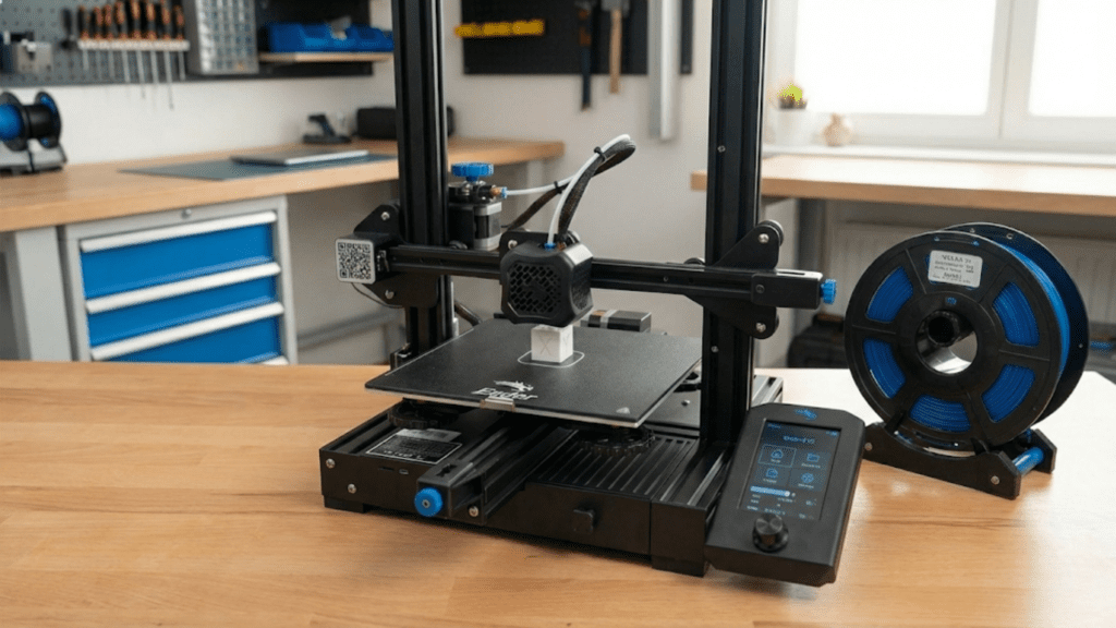
With the printer assembled, software configured, and bed leveled, you’re ready for that exciting first test print that validates everything works correctly.
Select a simple test object that’s small, doesn’t require supports, and prints relatively quickly. Many printers include pre-sliced test files on SD cards ready to print immediately. Common test objects include calibration cubes, small figurines, or simple shapes. For your very first print, using included test files eliminates slicing software as a potential problem source.
If slicing your own test object, choose conservative settings. Use standard layer height around zero point two millimeters, moderate print speed around fifty millimeters per second, and full part cooling after the first layer. These forgiving settings maximize the chance of success rather than testing limits.
Load filament into the printer following your printer’s specific filament loading procedure. Most printers require heating the hotend to printing temperature, then feeding filament through the extruder until it emerges from the nozzle. Some printers include automatic filament loading functions that feed filament once you insert it. Verify plastic extrudes smoothly and consistently from the nozzle before starting your print.
Insert the SD card with your test file or prepare to send the file via USB. Start the print and watch closely, especially the first layer. The first layer tells you immediately whether bed leveling and adhesion are correct. Don’t walk away during the first layer, your vigilant observation catches problems early before wasting material on failed prints.
Watch the first lines go down and assess adhesion and appearance. Lines should stick firmly to the bed without being dragged by the moving nozzle. They should appear slightly flattened against the bed, showing the characteristic “squish” of proper first layer height. Lines should be consistent width without gaps between adjacent lines.
If the first layer looks wrong, don’t hesitate to stop the print and make adjustments. If lines aren’t sticking or appear tall and round, the nozzle is too far from the bed and you need to reduce Z-offset or relevel. If lines are translucent or being scraped by the nozzle, it’s too close and you need to increase Z-offset or raise the bed slightly. Make adjustments and restart rather than wasting time and material on prints destined to fail.
If using live Z adjustment, watch the first layer and make real-time corrections to dial in perfect height. Adjust in small increments, perhaps zero point zero five millimeters at a time, allowing several lines to print after each adjustment before evaluating whether more adjustment is needed. When lines look perfect across the entire first layer, note the Z-offset value you’ve achieved for use in future prints.
Once satisfied with the first layer, you can relax slightly though continue monitoring periodically. Watch for signs of problems including layer shifts, under-extrusion, stringing, or the print detaching from the bed. Most issues manifest early, and prints that make it through the first several layers usually complete successfully.
When the print completes and the bed cools, remove the print carefully. Use the printer’s tools or a spatula to gently lift the print from the bed. For your first print, the object quality matters less than the accomplishment of completing a print successfully. Even if quality isn’t perfect, a completed print validates your setup work and proves the printer functions.
Evaluate the completed test print. Check for dimensional accuracy if the model has known dimensions. Examine surface quality looking for layer consistency, good bridging and overhangs, and minimal defects. Don’t expect perfection on first prints, but obvious problems like severe layer separation, extensive stringing, or wildly inaccurate dimensions indicate issues requiring troubleshooting.
If the first print succeeds reasonably well, congratulations. You’ve successfully set up your 3D printer and demonstrated it works. If the first print fails or shows significant problems, use systematic troubleshooting to identify causes. Refer to previous articles on first layer problems, bed leveling, and other topics. Consult your printer community for help with specific issues.
After initial success, print several more test objects to build confidence and familiarity with printer operation. Each successful print reinforces correct procedures and builds your understanding of what normal operation looks and sounds like. Variety in test prints helps you understand how the printer handles different geometries and features.
Conclusion: You’re Ready to Print
Completing the setup process from unboxing through successful first prints represents a significant accomplishment that shouldn’t be minimized. You’ve transformed a box of components or an inert assembled machine into a functional creative tool that can bring digital designs into physical reality. The knowledge and skills you developed during setup, from understanding mechanical assembly to calibrating the bed to operating slicing software, form the foundation for all future printing success.
The setup process might have been smooth and completed quickly, or it might have involved challenges, frustrations, and troubleshooting that tested your patience. Both experiences are normal and valid. What matters is persistence through any difficulties and systematic approach to solving problems rather than giving up or taking shortcuts that create future issues. The problem-solving skills you developed during setup serve you well throughout your printing journey as you encounter new challenges and learn to overcome them.
While setup is complete, learning continues indefinitely. Your first prints taught you what successful printing looks and feels like, providing baseline experiences for recognizing when future prints aren’t going quite right. Each subsequent print adds to your accumulated knowledge, building intuition about printer behavior, material characteristics, and model design considerations. The learning curve never truly ends, but it becomes progressively gentler as foundational knowledge grows.
Routine maintenance keeps your printer operating reliably after initial setup. This includes regular bed cleaning and leveling checks, periodic lubrication of linear rails and lead screws, belt tension verification, and replacing consumables like nozzles when they wear. Establishing maintenance habits now prevents degradation of print quality over time and extends printer lifespan. A well-maintained printer rewards your care with consistent reliable performance.
Documentation of your setup process and initial settings proves valuable for future reference. Note your successful Z-offset values, record any custom firmware configurations, photograph proper assembly for reference if you ever need to disassemble components, and maintain logs of what settings work well for different materials. This documentation becomes your personal knowledge base that accelerates troubleshooting and optimization.
Community involvement enriches your 3D printing experience beyond just technical success. Share your first prints, ask questions when stumped by problems, and eventually help others with challenges you’ve overcome. The 3D printing community thrives on this knowledge sharing, and participating in it connects you with fellow enthusiasts who share your interest and can provide support throughout your journey.
Looking forward, the printer you’ve just set up opens remarkable creative and practical possibilities. From printing replacement parts for household items to creating custom tools, from producing gifts and decorations to prototyping inventions, from making artistic sculptures to engineering functional mechanisms, your 3D printer enables bringing imagination into reality. The projects you’ll complete, skills you’ll develop, and satisfaction you’ll experience from successful prints make the setup effort worthwhile many times over.
The journey from beginner anxiously opening a box to confident printer operator producing quality prints takes time and involves inevitable challenges. But with proper setup completed, patient learning, and community support, virtually anyone can master 3D printing fundamentals and achieve results that initially seemed impossibly complex. Your successfully set up printer stands ready to help you learn, create, and bring your ideas to life. Enjoy the journey ahead!