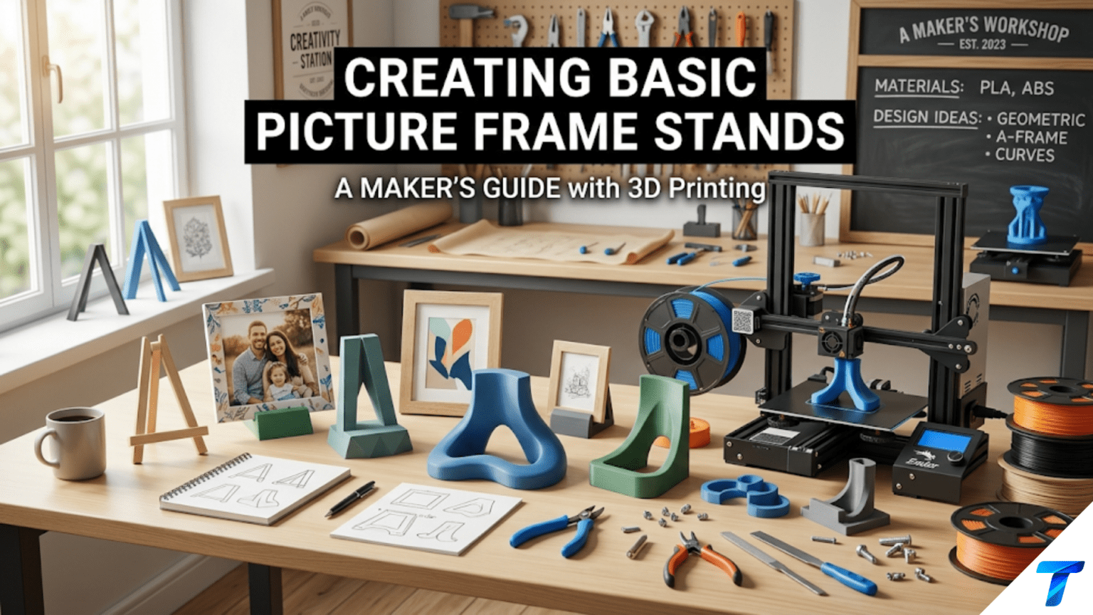
3D printed picture frame stands are custom-designed supports that hold photo frames, artwork, signs, and decorative tiles upright on shelves, desks, and tabletops. They are practical beginner projects because they require only simple geometry — angled supports and a base — yet teach several important design skills including calculating stable tilt angles, designing for load-bearing applications, and creating parts that interface precisely with existing objects.
Introduction: The Humble Stand That Makes Everything Display-Ready
There is a category of object that exists entirely in service of something else — whose whole purpose is to present another object beautifully while remaining invisible itself. The picture frame stand is precisely this kind of object. When it works, you don’t notice it. You notice the photograph, the artwork, the sign, the memento it’s displaying. The stand simply holds things up.
But when a frame stand is missing, inconvenient, or the wrong size, it becomes very noticeable — a frame that has to lean against a wall because it has no stand, a treasured photo that can only be displayed when there happens to be a wall to hang it on, a collection of small art tiles with nowhere to stand.
3D printing solves the picture frame stand problem with elegant specificity. You can print a stand for the exact frame you have, sized to hold it at exactly the right angle, in a color that disappears against any surface or complements the frame’s finish, with a design refined to exactly the aesthetic you want. And you can print dozens of them — one for every frame, every shelf, every angle — for the cost of a few grams of filament each.
Beyond the practical value, picture frame stands are excellent learning projects. They introduce the concept of designing for a specific load and geometry: the stand must support the weight of the frame, hold it at the right angle without tipping, and interface with the frame’s specific back edge. These constraints teach the kind of functional design thinking that transfers to every support structure, bracket, and mounting project you’ll ever make.
This guide covers the full spectrum of picture frame stand design: the different styles and their applications, the dimensional analysis that determines whether a stand will hold its frame stably, material choices, slicer settings for functional supports, finishing techniques, and a range of creative variations worth exploring.
Understanding Stand Geometry: What Makes a Stand Work
Before designing or printing any stand, understanding the geometry that determines stability is essential. A stand that looks right on screen may tip forward when a frame is placed on it. Understanding why — and how to prevent it — is fundamental to good stand design.
The Stability Triangle
A picture frame on a stand forms a system with three contact points with the surface below it: the two feet of the stand and the bottom edge of the frame where it contacts the stand’s support ledge. The stability of the system is determined by the relationship between the center of gravity of the frame+stand assembly and the base footprint defined by these contact points.
If the center of gravity falls within the triangle defined by the three contact points, the system is stable. If it falls outside — most commonly in front of the front contact point — the system tips forward.
Practical implication: Stands need either a wide base (pushing the front contact points forward) or a significant rear extension (moving the rear contact points back) to ensure stability with the weight of the frame above. Taller, heavier frames need more stable bases than short, light ones.
Viewing Angle
The angle at which a frame is displayed — how far it tilts back from vertical — affects both aesthetics and stability. Common viewing angles are:
| Display Context | Typical Tilt from Vertical | Notes |
|---|---|---|
| Desk or tabletop, seated viewer | 10–20° | Slight backward tilt for comfortable viewing while seated |
| Shelf at eye level | 5–10° | Minimal tilt; nearly vertical |
| Low shelf, standing viewer | 15–25° | More tilt to angle display toward standing viewer |
| Tabletop display piece | 15–30° | More visible from standing height |
| Cookbook/recipe holder | 30–45° | Steep angle for reading at counter height |
The viewing angle is determined by the geometry of the stand — specifically, the height of the support ledge relative to the depth of the base. Taller ledge + shorter base = steep angle; shorter ledge + longer base = shallow angle.
The Three Stand Configurations
All picture frame stands fall into one of three basic configurations:
Easel style: A three-legged easel shape — two front legs and one rear leg that spreads backward. The frame leans against the front legs and the rear leg provides the stabilizing base. Classic for lightweight frames, photo cards, and small art prints.
Kickstand style: A flat backing plate that attaches to or leans against the back of the frame, with a single hinged or fixed leg that kicks out behind to prop the frame forward. This is the style used in most commercial photo frames. For printed versions, the kickstand is a separate piece that the frame leans against.
Groove/slot style: A base with a slot or groove that the bottom edge of the frame slides into. The frame stands in the slot at an angle determined by the slot geometry. This is the simplest and most stable design for frames that will be displayed long-term in a fixed position.
Stand Types and Their Designs
Type 1: Simple Groove Stand
A rectangular base with a slot cut into the top surface at the desired angle. The frame’s bottom edge sits in the slot, held at a fixed angle. This is the simplest possible stand design — just a solid block with a groove — and it’s remarkably effective.
Design specifications:
- Base dimensions: Width = frame width + 10–20mm clearance on each side (or narrower for a minimal look, down to 60% of frame width for stable lightweight frames); Depth = 60–100mm
- Base height: 20–40mm
- Slot width: Frame thickness + 1–2mm clearance (tight enough to hold the frame without wobbling)
- Slot depth: 10–15mm (deep enough to capture the frame securely)
- Slot angle: The slot is cut at the desired display angle from vertical — for a 15° tilt, the slot is angled 15° from vertical
Best for: Fixed displays where the frame won’t be moved frequently, heavier frames that need solid support, decorative tiles and plaques without their own stands.
Design tip: The slot can be designed to accommodate different frame thicknesses by making it slightly tapered — wider at the top, narrower at the bottom. This works for a range of frame thicknesses and provides a secure “wedge” fit.
Type 2: Easel Stand
A three-legged easel form. Two legs support the front of the frame; a third leg extends backward to provide stability. The frame leans against the two front legs at an angle determined by the rear leg length.
Design specifications:
- Front legs: 2 uprights, typically 15–25mm wide, 3–5mm thick, tall enough to support the desired frame height
- Rear leg: Single leg extending backward from a pivot point at the top of the front assembly; its length determines the display angle
- Front ledge: A small horizontal shelf at the base of the front legs where the frame’s bottom edge rests
- Connection: The rear leg connects to the front legs either rigidly (one-piece print at a fixed angle) or with a hinge (adjustable angle)
Print-in-place easel: A hinged easel that prints assembled, with the rear leg hinged to the front assembly. The hinge uses the print-in-place technique from Article 80 — the gap tolerance must be correct for your printer.
Fixed angle easel: Simpler and more reliable — the rear leg is printed at a fixed angle, the whole stand is one piece. No hinge required, no tolerance issues.
Best for: Lightweight frames and cards, temporary displays, adjustable-angle applications.
Type 3: Kickstand/Ledge Stand
A flat platform with a rear support that holds the frame at an angle. The frame either sits on the platform’s front ledge or leans against a support wall. This is the most versatile design for a wide range of frame sizes.
Design specifications:
- Platform base: Flat rectangle, 60–100mm deep, frame width or narrower
- Front ledge: A small raised lip (5–10mm high) at the front of the platform that captures the frame’s bottom edge
- Rear support wall: A wall that rises from the back of the platform at the desired display angle, against which the frame rests
- The angle between the rear support wall and the base determines the display angle
Best for: Larger frames, heavier frames, stable long-term displays, any application where the frame needs to be easily removed and replaced.
Type 4: Clip-On Stand
A stand that clips to the back of the frame directly, rather than the frame resting against or in the stand. This requires measuring the frame’s back edge and designing a clip geometry that grips it.
Design specifications:
- Clip channel: A U-channel sized to slide onto the frame’s back edge (channel width = frame thickness + 0.3–0.5mm clearance; channel depth = 10–15mm)
- Support leg: A leg extending from the clip at the desired display angle
- Leg foot: A small foot on the leg that contacts the display surface for stability
Best for: Frames without existing stands, adding a stand to a wall-mount-only frame, gifts where the stand is added to a purchased frame.
Dimensional Analysis: Sizing a Stand for Any Frame
Rather than using arbitrary dimensions, sizing a stand correctly requires working from the specific frame you’re designing for. Here’s the analysis.
Step 1: Weigh the Frame
If possible, weigh the frame with its contents on a kitchen scale. This tells you whether you’re designing for a 50g card display or a 500g heavy photo frame — a significant difference for the stand’s required stability.
Lightweight (under 100g): Almost any stand geometry will work. Medium (100–300g): Standard designs with adequate base depth are fine. Heavy (300g+): Use a groove stand or wide-base ledge stand; narrow easels may be unstable.
Step 2: Measure the Frame
Measure:
- Frame width (the dimension parallel to the stand’s width)
- Frame height (how tall the frame is — determines how high the center of gravity is)
- Frame thickness (the back-to-front dimension — determines slot or clip width)
- Frame back edge profile (flat? Rounded? Grooved? Affects clip design)
Step 3: Calculate Required Base Depth
For stability, the stand’s base depth should satisfy the tipping angle requirement: the system shouldn’t tip forward under the frame’s weight when disturbed by a light push.
A practical rule of thumb: Base depth ≥ Frame height × tan(display angle)
For a 150mm tall frame displayed at 15° tilt: Base depth ≥ 150 × tan(15°) = 150 × 0.268 = 40mm
For a 200mm tall frame at 20° tilt: Base depth ≥ 200 × tan(20°) = 200 × 0.364 = 73mm
This calculation gives you the minimum base depth. Adding 20–30% margin provides comfortable safety. For heavy frames, use more margin.
Step 4: Calculate Display Angle from Stand Geometry
For a ledge/groove stand, the display angle is determined by the relationship between the rear support height and the base depth:
Display angle from vertical = arctan(slot_horizontal_offset / stand_height)
Alternatively, design the slot angle directly at the desired display angle.
Material Selection for Frame Stands
| Material | Suitability | Notes |
|---|---|---|
| PLA | Good | Easy to print; adequate for most stands; avoid hot environments (near sunny windows) |
| Matte PLA | Excellent | Best aesthetic; flat finish disappears visually; doesn’t scratch adjacent surfaces |
| PETG | Very good | More durable; better heat resistance; slightly flexible which helps grip |
| Wood-fill PLA | Excellent for aesthetics | Natural look complements wooden frames beautifully |
| Transparent/Clear PLA | Specialty | Near-invisible stand; showcases frame without visual clutter |
| TPU | For grip pads | Add TPU pad inserts to stand contact points for non-slip grip |
The Case for Transparent/Clear PLA
For frames with particularly beautiful finishes or for displays where the stand should be as unobtrusive as possible, transparent or near-transparent PLA produces a stand that is nearly invisible from normal viewing distances. The frame appears to float on the shelf surface.
Transparent PLA prints at standard PLA temperatures and requires slow print speeds and high cooling for maximum clarity. Even “transparent” FDM prints are translucent rather than optically clear due to layer lines, but at a glance from the normal viewing direction the stand effectively disappears.
Adding Non-Slip Surfaces
Stand contact points — where the stand meets the display surface and where the frame contacts the stand — should ideally be non-slip to prevent the frame from sliding. Options:
Printed TPU inserts: Design small recesses in the stand’s bottom surface and frame contact points, then print TPU pads that press-fit into these recesses. The TPU provides excellent friction against both the display surface and the frame.
Self-adhesive felt pads: Stick-on felt pads (available from hardware stores) applied to the bottom of the stand prevent sliding and also protect shelf surfaces from scratching.
Silicone dabs: A small dab of clear silicone sealant on each contact point, allowed to cure fully, creates a permanent non-slip surface.
Slicer Settings for Frame Stands
Frame stands are functional objects that must support loads reliably. Settings prioritize strength and dimensional accuracy over aesthetics.
| Setting | Recommended Value | Notes |
|---|---|---|
| Layer Height | 0.2mm | Standard; adequate for functional stand |
| Print Speed | 40–50 mm/s | Moderate |
| Perimeters/Walls | 4 | Good strength for load-bearing sections |
| Infill | 30–40% | Grid or Gyroid; stands need structural integrity |
| Top/Bottom Layers | 4–5 | Solid closure |
| Support | Only if needed | Design to avoid support on critical surfaces |
| Bed Adhesion | Brim (5–8mm) | Especially for stands with small base footprints |
| Cooling | 80–100% | Standard |
| Seam Position | Rear or base | Hide seam from visible faces |
Print Orientation for Stand Strength
The most critical design decision for a stand that will support a frame is print orientation — how the stand is positioned on the build plate.
For a groove stand (solid block with slot): Print upright with the base on the build plate. The compressive load of the frame presses down through the layers — the strong direction for FDM.
For an easel stand: Print with the front legs flat on the build plate if possible. The bending loads on the legs run parallel to the layer lines in this orientation.
For a ledge/kickstand stand: Print with the base flat on the build plate. The rear support wall prints vertically, with layer lines running parallel to the wall surface — strong in the compression direction the frame applies.
The general rule: Orient the stand so the primary load direction (the direction the frame’s weight pushes) runs parallel to the layer lines (through the layers in compression) rather than perpendicular (trying to peel layers apart in tension).
Step-by-Step: Designing a Groove Stand in Tinkercad
Let’s design a groove stand for a 4×6 inch (102mm × 152mm) photo frame.
Step 1: Determine Dimensions
Frame specs:
- Frame width: 130mm (the 4-inch dimension plus typical frame border)
- Frame height: 180mm (the 6-inch dimension plus border)
- Frame thickness: 12mm (measured with calipers)
Stand specifications:
- Stand width: 120mm (slightly narrower than frame — most stands are narrower than the frame they hold)
- Stand depth: 75mm (180mm frame height × tan(20°) = 65mm minimum, plus 15% margin)
- Stand height: 35mm
- Slot width: 13mm (12mm frame + 1mm clearance)
- Slot depth: 12mm
- Display angle: 20° from vertical
Step 2: Build the Base in Tinkercad
Create a box: 120mm × 75mm × 35mm. This is the solid base block.
Step 3: Create the Slot
The slot holds the frame’s bottom edge at a 20° angle from vertical. In Tinkercad:
- Create a thin box: 120mm × 5mm × 40mm (this represents the slot thickness × depth)
- Rotate it 20° from vertical (70° from horizontal) around the front-back axis
- Position it so the bottom of the slot opening sits at the top front edge of the base block
- Set this box as “Hole” and group with the base — the angled slot is now cut into the base
Step 4: Add Chamfer to Slot Opening (Optional)
Add a slight chamfer (angled lead-in) at the slot opening to make inserting the frame easier. Create two small triangular wedge shapes at the top of the slot, set as holes, and group.
Step 5: Round Base Corners
Use Tinkercad’s shape generators to find a “Rounded Box” generator, or manually add small cylinders at the base corners, set as solid, properly positioned to replace sharp corners with rounded ones.
Step 6: Add Rubber Pad Recesses (Optional)
Create 4 shallow circular recesses (10mm diameter, 1.5mm deep) in the bottom of the base at the four corners. These accept adhesive rubber or felt pads after printing.
Step 7: Export and Print
Export STL. In the slicer, orient the stand with the base flat on the build plate. Apply settings from the table. Print.
Step 8: Test Fit
Insert the frame into the slot. Verify:
- Frame slides in smoothly without forcing
- Frame holds at the desired angle without excessive wobble
- Stand doesn’t tip forward with the frame in place
- Slot is deep enough to hold the frame securely
Step-by-Step: Designing a Print-in-Place Easel
For lightweight frames, cards, and art prints, a hinged easel that adjusts to different display angles is a rewarding intermediate project.
Design Overview
The easel has three components:
- Front assembly: Two parallel legs with a horizontal ledge at the bottom
- Rear leg: A single leg that hinges to the top of the front assembly
- Hinge: A print-in-place pin hinge connecting the rear leg to the front legs
Key Dimensions
- Front legs: 15mm wide, 4mm thick, 120mm tall
- Cross brace between front legs: Creates rigidity
- Bottom ledge: 10mm deep, 5mm tall, prevents frame from sliding off
- Rear leg: 130–150mm long (longer = shallower angle; shorter = steeper angle)
- Hinge pin diameter: 5mm; bore diameter: 5.7mm (0.35mm radial gap for print-in-place)
Hinge Design
Following the print-in-place hinge principles from Article 80:
- 3 knuckles: 2 on the front assembly, 1 on the rear leg (interlocked)
- Knuckle length: 8mm each
- Gap between knuckles: 0.3mm
- Pin-bore radial clearance: 0.35mm (0.7mm total)
Print Settings for the Easel Hinge
The hinge requires the settings critical for print-in-place success:
- Layer height: 0.15mm
- Elephant foot compensation: 0.15mm
- Temperature: 5°C below standard (less fusion risk)
- Cooling: 100%
- Outer wall speed: 20mm/s
Working the Hinge Loose
After printing, work the hinge loose with gentle repeated flexing while the print is still warm. Once free, the easel adjusts to any angle from nearly flat to about 60° from vertical. A friction element (small TPU insert between the knuckles) can be added if you want the hinge to hold a specific angle.
Creative Picture Frame Stand Applications
Multiple-Frame Gallery Display Stand
A stand designed to hold 2–4 small frames side by side at slightly different heights — a miniature gallery display for a shelf. The base has multiple slots at different positions, each at a consistent angle, allowing a curated collection of small photos to be displayed as a unified group.
Business Card and Menu Display
The same groove stand design serves perfectly as a business card holder, restaurant menu display, or table number stand. Scale the dimensions to the specific item being displayed and adjust the slot angle for comfortable reading.
Recipe Card Holder
A sturdy groove stand with a slightly steeper angle (25–35°) designed for recipe cards or tablet-sized devices. The steeper angle puts the card at a good reading angle when the stand is on a counter at standing height.
Easel for Children’s Artwork
A larger-scale easel designed to display children’s drawings on a shelf or desk. Oversize slightly — 200–250mm tall front legs — to accommodate the larger paper dimensions of children’s artwork. Print in bright colors for a cheerful display stand.
Floating Frame Illusion Stand
A stand with a very thin, minimal profile — essentially just a thin-walled slot on a narrow base — that holds the frame while showing as little of itself as possible. The effect: the frame appears to float on the shelf. Best in transparent or white-matte filament.
Seasonal and Themed Display Stands
Stands with decorative elements incorporated into the base design — a stand with small stars or snowflakes around the base for holiday display, a stand with floral reliefs for spring, a stand with autumn leaves for a fall table. The frame displays the photo; the stand decorates the display area around it.
Graduated Height Display Set
A set of 3–5 stands at graduated heights (40mm, 55mm, 70mm, 85mm, 100mm base height) allowing photos of the same size to be displayed at different heights for a stepped gallery effect on a shelf. All stands use the same design, varied only in height.
Adapting Stands for Different Frame Types
Frames Without Stands (Wall-Hanging Only)
Many picture frames are designed only for wall hanging and have no integrated stand. A clip-on stand (Type 4 above) solves this problem. Design the clip to fit the specific frame’s back edge profile, print it in a matching color, and clip it on.
Very Small Frames (Wallet Size, Mini Frames)
Small frames — 2×3 inch or smaller — need proportionally smaller stands with narrower base widths and shallower slots. The same dimensional analysis applies; just scale everything down. For very small frames (under 70mm), wall thickness in the slot must be at least 3mm to maintain structural integrity.
Large or Heavy Frames (8×10 and Larger)
For frames above 200mm in any dimension, the stability requirements increase significantly. Use a groove stand rather than an easel, maximize base depth per the calculation, and print with 5 perimeters and 50% infill for the base section.
Frames with Unusual Profiles
Some decorative frames have unusually thick, thin, or oddly shaped back edges. Measure with calipers and design the slot or clip geometry specifically for the measured profile. Add 0.5–1mm clearance to the measured frame thickness for the slot width.
Digital Photo Frames
A digital photo frame sitting on a shelf with a generic stand often looks cluttered or unstable. A custom-printed stand sized exactly to the digital frame’s dimensions, with cable management for the power cord, produces a much cleaner display. Design a recess in the back of the stand base that guides the power cable neatly.
Troubleshooting Common Frame Stand Issues
Stand Tips Forward When Frame Is Placed In It
Cause: Base depth is insufficient for the height and weight of the frame; center of gravity falls in front of the front contact point.
Solution: Increase base depth by 20–30mm and reprint. Alternatively, add weight to the rear of the stand (place a small metal washer in a recess in the back of the base, secured with a drop of glue) to shift the center of gravity backward. For future designs, calculate minimum base depth using the formula above.
Frame Wobbles Side-to-Side in the Slot
Cause: Slot width is too large relative to the frame thickness, allowing lateral movement.
Solution: For existing stands, add thin strips of foam tape to the slot sides to reduce effective width. For future prints, reduce slot width to frame thickness + 0.5mm (tighter clearance).
Stand Slides on Shelf When Frame Is Removed or Replaced
Cause: Insufficient friction between stand base and shelf surface.
Solution: Apply self-adhesive felt or rubber pads to the base. Alternatively, add a thin strip of grip tape or silicone sealant to the base contact surfaces. Print TPU inserts for base recesses designed into the model.
Slot Depth Is Too Shallow — Frame Falls Out
Cause: Slot is not deep enough to capture the frame against light disturbance.
Solution: Reprint with slot depth increased to 15mm minimum. For existing stands, a small strip of foam tape applied to the back of the slot (reducing effective depth and increasing grip pressure) can partially compensate.
Hinge on Easel Won’t Move After Printing
Cause: Print-in-place hinge gap is too small for the printer’s tolerance, or temperature was too high causing fusion.
Solution: Work the hinge gently while still warm. If completely fused, increase the hinge gap by 0.15mm and reprint the easel. Reduce print temperature by 5°C for the hinge section (use a pause + temperature change if your printer supports it).
Stand Looks Rough or Ugly Compared to the Frame
Cause: Standard layer lines on a visible stand surface; material choice doesn’t complement the frame.
Solution: Print the stand in a material that either matches or intentionally contrasts the frame (wood-fill PLA for a wooden frame; matte black for a silver metal frame). Sand visible surfaces with 320-grit and 600-grit. Apply a light coat of spray paint or clear coat to unify the surface. Use 0.15mm layer height for a finer surface.
Building a Display System
Individual frame stands are useful; a coordinated system of stands transforms a shelf into a deliberate display. Consider building:
A coordinated color set: All stands in the same material and color — matte white, matte black, natural wood-fill — creates a unified backdrop that makes the frames themselves the visual focus.
A graduated height collection: Multiple stand heights allowing photos to be arranged at different levels for visual depth on a shelf.
A complete surface system: Stands for frames of every size you own — 3×5, 4×6, 5×7, 8×10 — so any frame can be displayed anywhere without searching for an appropriate stand.
Seasonal display stands: A set of plain stands plus a set of decorated seasonal stands that swap in for holidays and special occasions, changing the character of the display shelf throughout the year.
Conclusion: The Stand That Elevates Every Frame
A picture frame stand is, in physical terms, one of the simplest objects your printer can make. A block with a slot, or three legs with a ledge, or a flat base with a rear wall — the geometry is basic, the print time is short, the material cost is negligible.
But what the stand does is far from basic. It takes a photograph, a piece of art, a memento that was lying flat or propped against something — waiting for its proper place — and gives it one. It says: this thing is worth displaying properly. This image is worth seeing clearly, at the right angle, in the right light.
Every frame in your home that currently lacks a proper stand is waiting for this project. Every photo that lives in a drawer or leaned against a wall because there’s nowhere to display it properly is waiting for 20 minutes at your printer and a few grams of filament.
Print some stands. Put the photos up. Display the things that matter.
That’s what this project is for.