

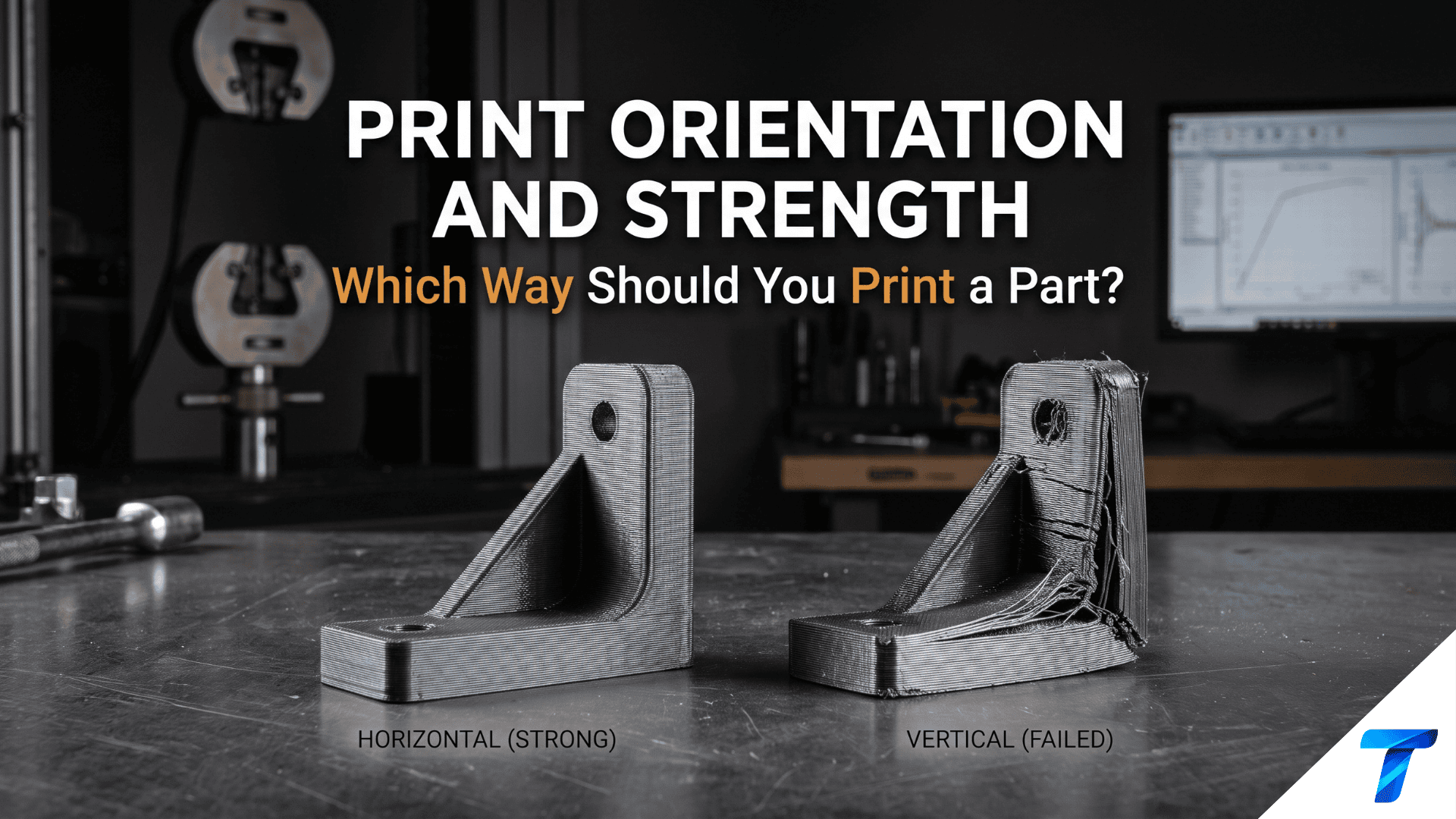

Print orientation decides whether a part survives load or snaps at the first layer line. A bracket printed flat can hold three times the force of the identical bracket printed upright. The reason is simple: FDM parts are layered, and layers are the weakest link. This guide shows you how to read load direction, pick the right orientation, and tune settings to recover strength you lose to geometry.
Quick Takeaways
- Layer lines are the weak point. Parts are strongest along the layers (X/Y axes) and weakest across them (Z axis), often by 30-60%.
- Orient so the main load runs parallel to the layers, never so it pulls layers apart.
- Flat-printed parts trade strength for support-free surfaces, while upright parts trade strength for a smaller footprint.
- Settings can recover 10-25% of Z strength: raise nozzle temperature, cut cooling, and add walls.
| Orientation | Relative Strength | Surface Quality | Support Needed | Best For |
|---|---|---|---|---|
| Flat (XY) | Highest in-plane | Excellent on top | Low | Plates, brackets, clips |
| On edge (XZ) | High bending strength | Good | Medium | Beams, hooks, levers |
| Upright (Z) | Lowest | Layer lines visible | Varies | Tall decorative parts |
Why Print Orientation Controls Strength
FDM printing deposits molten plastic line by line, then stacks those lines. Within a single layer, the filament fuses continuously along the extrusion path. Between layers, the new bead bonds to a bead that has already cooled. That interface never reaches full material strength.
This produces anisotropy: the part behaves differently depending on load direction.
- Intra-layer bonds (X/Y): Continuous strands carry tensile load like fibers in rope.
- Inter-layer bonds (Z): Thermal fusion across cooled surfaces, typically 40-70% of the strand strength.
Think of a stack of paper held together with weak glue. Pull the stack sideways along a sheet and it resists. Pull the sheets apart and it fails.
Typical Tensile Strength by Axis
Values below are representative for well-tuned prints on a stock 0.4 mm nozzle at 0.2 mm layer height. Your results vary with printer, filament brand, and settings.
| Material | XY Tensile (MPa) | Z Tensile (MPa) | Z Strength Retained |
|---|---|---|---|
| PLA | 50-60 | 25-40 | ~50-65% |
| PETG | 40-50 | 25-35 | ~60-70% |
| ABS | 35-45 | 15-30 | ~45-65% |
| Nylon (PA12) | 40-50 | 30-40 | ~70-80% |
| PC | 55-65 | 30-45 | ~55-70% |
| CF-Nylon | 70-90 | 25-40 | ~35-45% |
Carbon-fiber filled filaments show the biggest gap. Short fibers align along the extrusion direction, which boosts XY strength but does nothing to bridge layers.
The Three Print Axes Explained
X and Y: The Strong Directions
Loads applied along the X or Y axis stress continuous extrusion paths. The part resists tension, compression, and shear in the build plane. A flat plate loaded along its length is the strongest configuration you can print.
Z: The Weak Direction
A tensile load along Z tries to peel layers apart. Failure is sudden and clean, often with a flat fracture surface along a single layer line. Parts designed with the load along Z need either a reorientation or a design change.
Bending: The Special Case
Bending loads put one face in tension and the other in compression. The tensile face matters most. If layer lines run perpendicular to that tensile stress, the part fails at a layer boundary. For a beam, print it on its side or flat so layers run along its length.
How to Choose Orientation: A 5-Step Process
- Identify the load path. Mark where force enters the part and where it exits. Note whether it is tension, compression, bending, or impact.
- Draw the force vector. Layer lines should run parallel to tensile force, never perpendicular.
- Locate stress concentrators. Holes, fillets, snap hooks, and thin necks fail first. Keep their critical cross-sections in the XY plane.
- Check overhangs. Anything past 45-50 degrees needs support, which hurts surface finish and adds post-processing.
- Verify bed contact. Maximize flat surface area on the build plate for adhesion and warp resistance, especially with ABS and ASA.
Common Parts and Their Best Orientation
| Part Type | Recommended Orientation | Reason |
|---|---|---|
| L-bracket | Flat, with the long leg on the bed | Layers run along both arms |
| Hook or hanger | Flat, with the curve in the XY plane | Prevents delamination at the bend |
| Snap-fit clip | Flat, with the flex arm in the XY plane | Flex direction follows strands |
| Threaded hole in a block | Axis of hole along Z | Round holes print cleaner vertically |
| Gear | Flat | Teeth stay continuous and accurate |
| Pressure vessel or tube | Upright with high wall count | Hoop stress follows the layers |
| Shaft or axle | Flat if it carries bending load | Avoids layer splitting |
Settings That Recover Z-Axis Strength
You cannot eliminate anisotropy, but you can narrow the gap. Use these ranges as starting points.
| Setting | Strength-Focused Value | Effect |
|---|---|---|
| Nozzle temperature | +5-15 °C above standard | Better interlayer fusion |
| Cooling fan | 0-30% (ABS/PC off, PETG low) | Keeps layers hot during bonding |
| Layer height | 0.12-0.20 mm | Thinner layers give more contact area |
| Wall count | 4-6 | Walls carry most of the load |
| Infill | 30-50% gyroid or cubic | Diminishing returns past 50% |
| Line width | 110-130% of nozzle | Wider beads squish into layers |
| Print speed | 40-60 mm/s | Slower speed means longer heat soak |
| Enclosure | Required for ABS, ASA, PC, nylon | Stabilizes ambient temperature |
Walls matter more than infill. Moving from 2 to 5 walls usually increases part strength more than moving from 20% to 60% infill.
Example: Strength-Tuned Profile in PrusaSlicer Config Format
Paste these lines into a custom print profile .ini and adjust per material:
perimeters = 5
top_solid_layers = 5
bottom_solid_layers = 5
fill_density = 40%
fill_pattern = gyroid
extrusion_width = 0.48
layer_height = 0.16
perimeter_speed = 40
infill_speed = 60
This sets 5 walls, 40% gyroid infill, and wider extrusion at a moderate speed. Pair it with a nozzle temperature 5-10 °C above the filament’s midpoint.
Example: Klipper Cooling Override
To reduce cooling on the first interlayer-critical layers in Klipper, add this to the start of your slicer’s custom G-code:
M106 S0          ; fan off for strong layer bonding
SET_GCODE_OFFSET Z_ADJUST=0.0 MOVE=0
Then re-enable the fan only for bridges and overhangs using your slicer’s per-feature fan settings. For Marlin, M106 S0 works identically.
Orientation Trade-Offs: Strength vs. Everything Else
The strongest orientation is not always the best one.
| Factor | Flat | On Edge | Upright |
|---|---|---|---|
| Strength along length | Excellent | Good | Poor |
| Print time | Often fastest | Medium | Often slowest |
| Support material | Minimal | Moderate | Varies |
| Dimensional accuracy (XY) | Best | Good | Good |
| Surface finish | Smooth top, stair-stepped curves | Mixed | Visible layer lines |
| Warping risk | Higher (large footprint) | Medium | Lower |
| Bed adhesion | Best | Moderate | Weakest |
Tall, narrow parts also wobble during printing. An upright part over 100 mm tall with a small base often needs a brim, slower speeds, or a rotation.
Advanced Techniques
Split and Re-Glue
Cut a complex part into two sections so each prints in its ideal orientation. Join them with cyanoacrylate, epoxy, or acetone welding (ABS/ASA). Add alignment pins and mating surfaces to keep the joint stiff.
Non-Planar and Rotated Slicing
Some slicers support non-planar layers and angled slicing, which let layer lines follow curved load paths. This is still experimental on most hardware but can improve strength on curved brackets and pipes.
Annealing
Annealing PLA at 60-80 °C for 1-2 hours increases crystallinity and can improve interlayer strength and heat resistance. Expect 0.5-3% shrinkage, so design for it. Use HT-PLA or PLA+ formulated for annealing for the best result.
Fiber-Reinforced Layers
Continuous fiber printers lay fiberglass or carbon strands inside the part. They offer big gains in XY strength, but the Z weakness remains, so orientation still dominates.
Real-World Use Cases
Drone frames. Arms print flat with 4+ walls and carbon-fiber nylon. Layers run along the arm, which handles motor thrust and crash loads. Printing them upright would snap at the first hard landing.
Automotive brackets. Under-hood brackets in PC or CF-nylon go on the bed flat so tension runs parallel to the layers. Engineers keep bolt holes in the XY plane to avoid delamination around fasteners.
Tool holders and wall hooks. The hook curve prints flat so the hanging load pulls along the strands. A vertical hook often splits at a layer line under weight.
Enclosures with screw bosses. Print the shell with the open side up. Screw bosses grow vertically, so reinforce them with fillets and extra walls. Heat-set inserts handle load better than self-tapping screws into vertical bosses.
Hinges and living hinges. Print flat with the hinge axis in the XY plane. PETG and nylon hold up best, since flexing repeatedly stresses interlayer bonds.
Jigs and fixtures. A manufacturing jig that clamps parts in place usually prints flat for dimensional accuracy, with alignment pins printed upright only if short.
Common Orientation Mistakes
- Printing a hook upright. The bend becomes a stack of weak layer interfaces.
- Placing bolt holes along Z in a load-bearing flange. Clamping force peels layers apart.
- Ignoring support scarring. A strong orientation that needs heavy support may leave a rough surface exactly where a bearing or seal goes.
- Over-relying on infill. Walls and orientation beat infill percentage for strength.
- Skipping test prints. Print one coupon per orientation and break it. Ten minutes of testing beats a failed part in the field.
FAQ
Which print orientation is strongest for 3D printed parts?
Printing flat on the build plate gives the highest strength when the load runs along the X or Y axis, because layers run parallel to the force. Strength typically drops 30-60% when the load pulls layers apart along Z.
Does print orientation affect strength more than infill?
Yes. Orientation and wall count influence strength more than infill percentage. Changing from vertical to flat can improve failure load by 2-3x, while raising infill from 20% to 60% usually adds far less.
How can I make Z-axis layers stronger?
Raise the nozzle temperature by 5-15 °C, reduce or turn off the cooling fan, use thinner layers, slow the print speed, and print in an enclosure. Annealing PLA or choosing nylon and PC also helps.
Should I print a part vertically or horizontally?
Print horizontally (flat) for load-bearing parts such as brackets, hooks, and clips. Print vertically only when load runs along the layers, when you need round holes or cylinders to stay accurate, or when the footprint must stay small.


